OPERATE AND MAINTAIN AUXILIARY SYSTEMS
(Extracts courtesy of A.N.T.A. publications, Ranger Hope © 2008 www.splashmaritime.com.au)
Deck Machinery and Steering Gear
Deck Machinery and Steering Gear
Precautions in Deck Machinery Operations
Wire and Pulley, Chain and Box, Push - Pull Cable
Requirements for Steering Gears
Common items of deck machinery found on small vessels are the anchor windlass, winches and the crane or derrick.
The anchor windlass is used for handling anchor chain. It is usually located in an exposed position on the fore-part of the vessel, hence most of its moving parts are enclosed. Routine maintenance is usually carried out through the provision of grease nipples. Inspection of the equipment frequently involves the opening of plates or panels in the cover.
Figure 1 shows a typical anchor windlass. The cable lifter (or gypsy) can be clutched to the drive shaft by means of a simple dog clutch arrangement. The braking arrangement is usually a band brake. Warping drums may be provided at the ends of the drive shaft. These are used for heaving mooring ropes.
Maintenance Of Anchor Windlass
Maintenance should be strictly carried out as per the equipment manufacturer’s instructions. However, general guidelines for maintenance are suggested as follows:
Weekly
• Charge all grease points.
• Operate clutch through full travel.
• Operate windlass.
Six Monthly
• Inspect clutch plates and inspect for wear and corrosion
• Examine mechanical brake for wear.
• Examine base and mountings for corrosion.
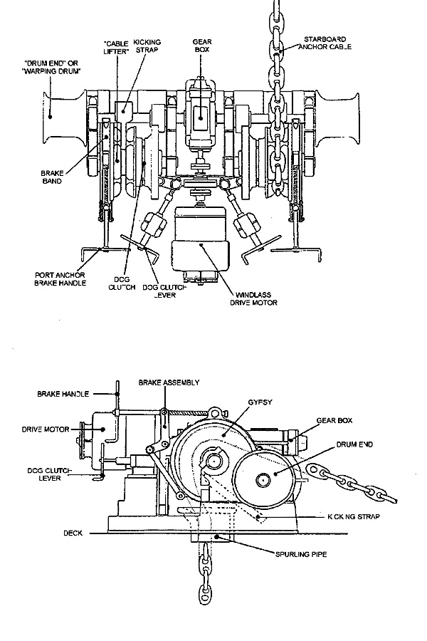
Fig. 1 Anchor Windlass
Winches are used to haul wires or ropes. They may be hand operated or driven by an electric or hydraulic motor or a steam engine. Basically they consist of one or more rotating drums on which a rope or wire may be wound and in some cases stored. A winch with a drum rotating on a vertical axis is known as a capstan. Winches are widely used with cranes, derricks and for mooring purposes.
Maintenance Of Winches
A winch requires the same care and maintenance as a windlass. In addition you must check the condition of the associated wires and ropes prior to use to ensure that they are free from breaks or frays. Wires should be regularly coated with a lubricant to protect them from corrosion.
Modern cranes rely on a vessel’s power to electrically or hydraulically operate winch drums and slewing gear. On many cranes three motions are possible - lifting, slewing and luffing (raising or lowering the jib boom). Figure 2 shows a crane where lifting and slewing motions are possible.
Cranes should always be marked with their Safe Working Load.
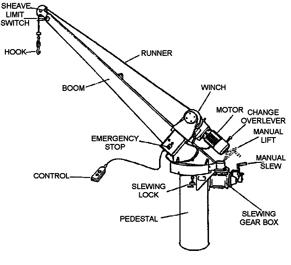
Figure 2 Slewing Davit Crane
Maintenance of Cranes
Suggested maintenance schedule for cranes (similar to the one shown in fig 2):
Weekly
• Turn davit boom through normal arc by hand slewing gear.
• Check winch brake for freedom of action.
• Inspect brake lining for wear and grease deposits.
• Conduct running test with dummy load. Failure of this test will probably require the replacement of brake linings.
Monthly
• Lubricate and grease all points on the crane.
• Check oil levels.
• Check brake linings for wear.
• Clean and examine all wire ropes and lubricate running gear.
Six Monthly
• Examine all parts for corrosion, distortion, cracks or any other defects.
• Check slewing gear for backlash.
• Check hand raising clutch, brake assembly and gear box clutch for damage, wear, and oil contamination.
The survey requirements for deck machinery are laid down in the National Standards. After the initial commissioning survey, deck machinery is surveyed during annual and periodic surveys or as required by the appropriate authority. The surveys include the inspection of windlass mounting and surrounding deck to insure that these are adequate for their task and have not deteriorated with use or due to corrosion. It is a requirement that the machinery should operate as specified and within safe limits.
Any gear (including cranes) used for handling cargo must comply with Commonwealth regulations contained within Marine Orders Part 32 (Cargo and Cargo Handling - Equipment Safety Measures)
Precautions In Deck Machinery Operations
• Ensure that operating and control handles are clearly marked to show ‘heave in’ and ‘pay out’ directions.
• Never exceed the safe working load of the equipment.
• Never operate the machinery if there is a fault in the clutch or brake.
• Ensure that gear wheels and other moving parts are always protectively covered.
• Keep the working area free from oil and grease.
• Do not operate the machinery if you cannot sight the load.
• Ensure that you know how to stop the running machinery in an emergency.
Always use the machinery in the manner specified, and within the limits suggested by the manufacturer.
Most vessels are steered with the aid of a rudder, which is rotated to the required angle by a steering mechanism. The type and size of steering mechanism depends on the size and design of vessel.
The National Standards specify the sizes and materials used for the construction of rudders. Two methods of mounting the rudder are shown in figure 3.
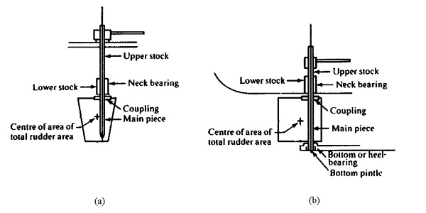
Figure 3 Rudders
Drawing (a) shows a mounting arrangement where the forces on, and the weight of the rudder are carried by the rudder stock. This means that the stock and bearings should be of adequate size and strength to withstand stresses under any weather condition.
Drawing (b) shows a pintle type rudder arrangement. The rudder is hung on pintles and has a further pintle in the extension to the keel.
The rudders are secured to the stock by flanged couplings and these need to carefully checked whenever the vessel is out of the water.
There is usually a gland around the rudder stock to prevent water entry into the hull. This needs to be checked regularly and possibly the packing or seals renewed when the vessel is in a safe situation (usually out of the water).
Next lets consider the mechanisms used to rotate the rudder, i.e. the steering gear. These can range from a simple wire and pulley system to a more complex electro-hydraulic one.
A wire and pulley arrangement is shown in figure 4. which consists of a wire wound around a drum fitted to the wheel. The wire passes through a series of pulleys on the two sides which connect to the tiller or quadrant of the rudder mechanism. To avoid excessive strain and bending of the wire the pulley blocks should be as big as possible and positioned to avoid an excessive angle or be easily fouled. Buffer springs are provided on both port and starboard to prevent violent recoil of the steering wheel. All components should be inspected and greased or oiled as appropriate.

Figure 4 Wire and Pulley
Chain And Box
A wide variety of chain and box installations make use of automotive parts such as shafts, universal joints and truck steering boxes. These systems require periodic inspection and lubrication. The chain is liable to stretch and should be checked regularly. For this reason the chain length is usually adjustable.
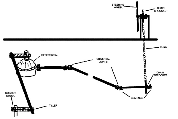
Figure 5 Chain and Box Gear
Push-Pull Cable
A push-pull cable type steering arrangement is shown in figure 6. This arrangement is similar to that used on outboard motors. The length of the cable should not be too long or short as this can affect the tiller response. If the push-pull cable or rod seizes, there must be provision for releasing the push-pull rod from the tiller to operate the emergency steering.
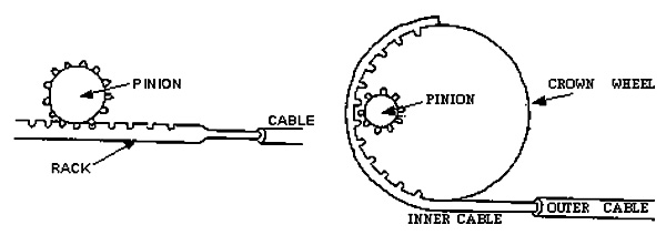
Figure 6 Push-Pull Cable Gear
Hydraulic systems are common in vessels of 20 metres or more in length. These systems range from simple manual systems to electro-hydraulic ones. Figure 7 shows a simple manual system with a single steering station.
The system operates utilising the flow of hydraulic fluid under pressure to control the movement and position of the rudder. The system consists of a two way hydraulic pump, usually an internal gear pump, connected to the wheel. Two pipes lead from the pump to the hydraulic cylinder and ram, which in turn is connected to the tiller. The rotation of the wheel will force oil from the pump to one side of the ram thus rotating the rudder.
A major problem associated with any hydraulic system is air in the system therefore, most systems are built to be self purging of air.
The emergency steering will require the oil to be by-passed and a valve is placed between the two sides of the system for this purpose. To prevent hydraulic locking, this valve will need to be opened when the emergency system is to be operational. In addition, there should be a relief valve which spills the oil from one side to the other in the event of shock loading to the system.
Specific maintenance requirement for this system is to ensure that the oil level is adequate and that there are no leaks.

Figure 7 Simple Hydraulic System
Simple Telemotor
In most larger systems the signal from the steering wheel is transmitted to the steering gear by means of a telemotor. This not only ensures that the steering system is isolated to the steering flat, it also means that the steering system can be used even if the wheel and connections are damaged or become inoperative.
Figure 8 shows a steering system incorporating a telemotor. The latter consists of a transmitter in the wheelhouse and a receiver in the steering flat. The movement of the wheel activates an hydraulic piston in the transmitter. The fluid displaced by this piston is used to displace a similar piston in the receiver. This movement is used to control the main steering gear’s hydraulic pump, which in turn operates the steering gear and rudder. The receiver is usually spring loaded so that the steering wheel will easily return to the midships position.
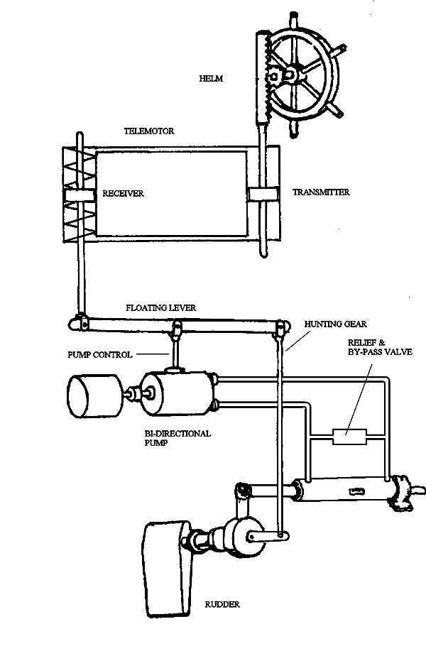
Figure 8 Steering Gear and Telemotor
Electro-Hydraulic
The electro-hydraulic system, shown in figure 9, has the advantage that the signal from the wheelhouse to steering flat is transmitted by electrical wires. Further, the system uses a uni-directional pump which is less complicated and cheaper than a bi-directional.
The pump supplies oil at a constant rate to a directional control valve, which is usually positioned in the steering flat.
The valve consists of three positions, and depending on the position, will supply oil to either side of the double acting ram. When in the neutral position, oil is locked in the ram, thus maintaining the given rudder angle, whilst the pump flow is circulated back to the tank. The valve is operated by solenoids controlled from the wheelhouse via the control box.
As with the previous system there is a by-pass and relief valve fitted between the left and right sides of the ram. Emergency steering can be carried out by operating the emergency steering lever located in the steering flat.
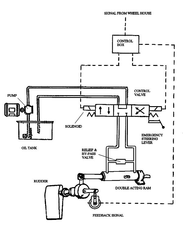
Figure 9 Electro-hydraulic System
Requirements for Steering Gears
Steering Gears are surveyed during a vessel’s annual and periodic surveys. The requirements for steering gears are laid down in the National Standards for Commercial Vesels. These are summarised below:
General Design
• All vessels except twin screw vessels and vessels where the normal means of steering is a hand tiller shall be fitted with two independent means of steering.
• The steering gear shall be of adequate strength to steer the vessel at maximum speed both ahead and astern.
• Rudder movement should be 35 degrees port and starboard.
• In vessels 12.5m and over the steering gear shall be capable of putting the rudder from 35 degrees on one side to 30 degrees on the other in 30 seconds at maximum speed.
• The steering gear shall be so designed and constructed to prevent violent recoil of the steering wheel.
• In hydraulic systems, changing over from primary to secondary systems should be able to be carried out easily and quickly.
• Power driven hydraulic systems shall be fitted with a relief valve to prevent mechanical damage.
• The rudder indicator shall move in the same direction and give a true indication of the rudder angle.
• If the emergency steering is remote from the steering/navigation position an adequate form of communication between these two positions shall be installed.
• Where necessary the steering gear will be fenced and have adequate guards to avoid injury to personnel.
As stated above if the tiller and hence the rudder is rotated by hand as in small vessels it is not required to have a back up or emergency system. However, in most modern vessels a mechanical means is employed to move the tiller, thus requiring an emergency back up. This may take the form of a hand tiller, which can be quickly and easily fitted to the top of the rudder stock. This emergency tiller must be kept in a place close to the steering flat and stock.
Survey Requirements
A National Standards typical survey schedule may be:
Annual Survey: Operational test of main and emergency means of steering.
2 Yearly Survey: Inspection of Rudders.
8 Yearly Survey: Steering gear.
Operation, Testing and Drills
The National Standards contains detailed procedures concerning the safety of navigation. These procedures are summarised below:
• If the vessel is fitted with an automatic pilot the manual steering shall be tested after prolonged use and before entering areas where navigation requires special caution.
• Within 12 hours before departure the vessel’s steering systems shall be checked and tested, where applicable by the operation of the following:
1. the main steering gear
2. the auxiliary system
3. the remote steering gear control system
4. the wheelhouse steering position
5. the emergency power supply
6. the rudder angle indicators
7. the system power failure alarms.
• Tests and checks shall include:
1. the full and accurate movement of the rudder
2. visual inspection of all parts and linkages
3. the operation of the means of communication between the wheelhouse and steering gear compartment
• Simple operating instructions and a block diagram should be permanently displayed in the wheelhouse and steering gear compartment.
• Emergency steering drills shall take place at least once every three months.
• Details of all tests, checks and emergency steering drills shall be recorded in the log book or the vessel record book.
Tanks perform two important tasks on a vessel. In addition to storing liquids, they provide a second skin to the vessel when located in the bottom or sides. Hence, they provide a very important watertight barrier against flooding.
Figure 10 shows a typical tank arrangement in a 24 metre vessel. Each of the tanks has a specific purpose and are either interconnected or kept separate from each other by a pumping system.
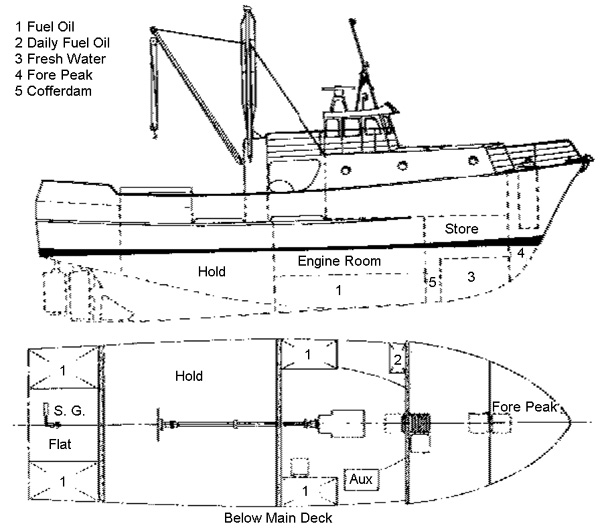
Figure 10 Tank Arrangement
Tanks may be provided for the storage of:
• Fuel oil
• Lubricating oil
• Ballast water
• Fresh water
• Sewage
• Oily bilge water
• Cargo
In vessels of less than 24 metres length, fuel may be stored in a number of tanks which may either form part of the hull or be free standing as shown in figure 11. Note: that figure 11 depicts all the fittings that a tank can have, but not all tanks are thus fitted. e.g. double bottom tanks don’t have a saveall.
1, 16, & 17 Tank Venting
All fuel tanks are required to be vented to atmosphere (not into the vessel). The vent or breather will terminate in a gooseneck or similar arrangement, which prevents water from entering the tank down the vent. If the vent pipe is greater than 18 mm in diameter, the outlet will be fitted with a wire gauze screen or ‘flame trap’.
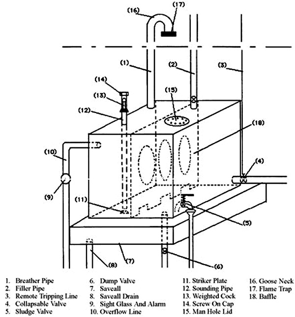
Figure 11 Tank Components
2. Filler Pipes
These are arranged so that any spillage will not enter the vessel. Therefore, the inlet or delivery end of the filler pipe is located outside the vessel and will have a valve and/or a water tight cap/blank. The pipe between the deck and the top of the tank may be flexible if necessary, but must be of reinforced synthetic type secured with corrosion resistant clips at each end. Note:- When transferring or re-fuelling, all precautions must be observed to prevent fire or spillage. This will comprise of all fire, pollution and spill control devices being ready. However, the best way to prevent these from happening is to ensure that the personnel involved are competent with the operation, procedures and safe working practices.
3. & 4. Tripping Line and Delivery valve or cock
All fuel tanks with discharges above the bottom plates have shut off valves or cocks fitted as close as possible to each tank (preferably on the tank). These can be operated from a position outside the engine room, via a non-flammable connection, such as a steel wire
5. Sludge valve
It is necessary to remove contaminants, notably water, prior to the fuel being delivered to the engine. Therefore, fuel tanks are fitted with sludge valves, which are self closing. If this type of arrangement is not fitted, the sludge and water may be drained through the drain valve or plug.
6. Dump - Drain Valve or Plug
In the event of the tank rupturing or for inspection purposes, all fuel tanks which are not double bottoms must be fitted with a method of draining them into another storage tank (not the bilge).
7. & 8. Saveall and Drain
Because free standing tanks may be fitted ‘high’ in the engine room, it is necessary to have drip trays fitted to them so as to prevent any leakages onto machinery below. These savealls will also need to be drained, with the drain pipe leading to a drain tank.
9. & 10. Overflow Sight Glass & Alarm
When filling or transferring fuel there is always a danger that there may be a spillage. Due to pollution and fire hazards associated with fuel oil, it is usual for tanks to be fitted with an overflow pipe which leads to either an overflow tank or to a double bottom fuel tank. These overflows are also fitted with a sight glass and audible alarm.
11. 12. 13 & 14. Sounding Pipe, Striker Plate, Weighted Cock & Screw on Cap
Some method of measuring the contents of the tanks is fitted to the tank. This can either be a dial gauge or sight glass. However, most tanks will be fitted with some method by which the contents can be measured or sounded by a sounding tape or dip stick. The sounding pipe will extend from the top of the tank to near the bottom and, fitted with a screw on cap-plug, and may have a self closing cock. At the bottom of the sounding pipe a striker plate is welded to the tank. to prevent a hole being ‘punched’ in the tank by the measuring device.’
15. Manhole
For tanks which have a capacity of more than 800 litres, a manhole or hand hole for cleaning and inspection purposes will be provided either on the top or on the sides of the tank. Areas such as the top or bottom of tank where water and condensation will accumulate, are prone to corrosion. These areas will need a close inspection. The bottom of the sounding pipe is another important area since if this corrodes out the sounding device may become ‘jammed’ in the pipe.
18. Baffles
Baffles spaced not more than 1 m apart are fitted to reduce the free surface effect.
If the tank is fitted with a sight glass, this must have self closing cocks at the top and bottom. Under no circumstances must these cocks be wired open - as they will prevent a spill should the glass break.
Typical Layout
Figure 12 shows a vessel fitted with four main fuel oil storage tanks and one day tank for the main engine. As can be seen the fuel can be put into the storage tanks from the filling line on deck and transferred between tanks by the use of the fuel oil transfer pump(s). The transfer pump also delivers fuel to the daily service tank, which in turn delivers fuel to the engine. Some vessels may have two day tanks, thus the fuel return from the engines injectors should be changed over when the delivery is changed.
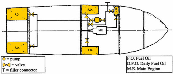
Figure 12 Fuel Oil System
Refuelling Precautions
• Understand and comply with all port regulations.
Ensure that all personnel involved with the operation, understand the systems and procedures for refuelling.
Moor the vessel securely.
Keep fire-fighting appliances in readiness.
Keep clean up equipment ready.
Plug scuppers on deck.
Extinguish open flames or cigarettes near fuelling operation.
Ensure tank vents are clear.
Fuel lines should be secured to prevent movement.
Pipe bends should be smooth and padded where they pass over sharp edges.
If necessary ensure that lines are earthed.
Ensure that incoming fuel is clean
Pipe joints should not leak.
Maintain a constant watch to monitor flow and prevent spills.
Close filler caps after fuelling.
Clean any spills on deck.
As with fuel, fresh water may be stored in any tank aboard the vessel. However, each of these liquids must only be stored in a tank designated for that purpose. This means that it should not be possible to pump fuel into fresh water or ballast tanks and vice versa. Furthermore, these tanks should be separated from each other by a cofferdam so that if there is a leak from a fuel or ballast tank, it does not contaminate the fresh water.
Fresh water storage tanks were traditionally coated internally with a cement wash. in order to protect the tank from corrosion and maintain the quality of water However, these days proprietary branded coatings are available to do the same job effectively. The protective coating on the inside of these tanks should be inspected and repaired or renewed at regular intervals.
Since the water quality may deteriorate over time it is also common practice for the fresh water used for human consumption to be thoroughly filtered and chemically treated with a small measured amount of chlorine to kill any bacteria. In some cases a UV steriliser is used.
To prevent the fresh water pump from starting and stopping every time a tap is used, fresh water systems usually incorporate a pressure tank or “nu-press” system. This tank has a buffer of compressed air, which allows water to be supplied under pressure, with the pump operating periodically to replenish the tank.
Each ballast tank is provided with means of filling, venting, sounding and emptying. Tanks may be filled by pumping or gravitating seawater into the tank. The latter is achieved by opening the sea inlet valves and lines to the tank and by-passing the pump, so that the water fills the tank by gravity.
In figure 13, No 1 is the sea water inlet valve. This fitting will need to be inspected/repaired when the vessel is on the slip. Outboard of this valve or cock will be a grating which prevents some of the larger solids from entering the system. On the inboard side of the valve will be a strainer (No 2), which ‘filters’ out the finer solids protecting the system from blockage and damage. The inboard strainer will need to be cleaned on a regular basis, thus the isolating valve (No 3). When the strainer is being cleaned care needs to be taken to ensure that the filter screen is clean and undamaged and the sealing surfaces and jointing material is in good condition. The sea water connection to the ballast system may be connected so the water can either be gravity fed or pumped into the system.
The pump (No 4) is usually an electrically driven centrifugal type. The discharge from the pump is connected to the ballast main, which is a pipe common to all of the ballast tanks. In the drawing the ballast tanks are the fore and aft peaks (Nos 10 & 13) and the double bottoms (Nos 8, 9 11, & 12).
To empty the tanks the appropriate tank, pump and overboard discharge valves are opened. It is not advisable to run any pump dry, therefore it is common practice, especially at the latter stages, to have the sea water inlet slightly opened to act as a lubricant and coolant, to the pump and to provide continuous priming.
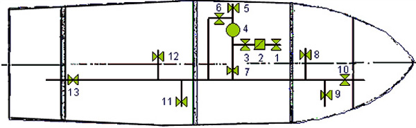
Figure 13 Ballast System
The purpose of a bilge system is to remove unwanted water and other liquids from within the vessel. Bilge level alarms are fitted to many bilges, in particular the engine room bilges. The audible alarm must have a power supply from both mains and emergency systems and the alarm must be clearly audible to a person at the steering position under all operating conditions.
Requirements
Other than in vessels less than 7.5 metres in length, all vessels must have two bilge pumps, which in vessels of up to 20 metres may be a combination of both power and hand driven. Beyond 20 metres both pumps must be power driven and have different sources of power. Each of these pumps will have a specified discharge capacity. A further requirement is that power driven pumps must be self priming or be provided with a suitable priming device.
All bilge suctions are required to be fitted with strum, strainer or mud boxes to prevent solids from entering and either blocking or damaging the system.
Back Flooding
Back Flooding, where sea water from the sea suction floods back through the system into a bilge space or water from one bilge space floods through the system into another, is not a desirable situation and may lead to the sinking of the vessel. Back Flooding must be prevented at all times and done automatically. This is achieved with the use of non return valves in each of the bilge pipes which prevent flow back into the compartments.
Typical Arrangement
Figure 14 shows a bilge system as fitted on a vessel of 20 to 25 metres in length. The system looks similar to the ballast system except that the valves are mainly screw down non return as opposed to screw lift. The sea water connection (No 4) acts as a primer for the pump and is used to flush the system after pumping bilges. The forward bilge suction is not into the fore peak but into the chain locker, whereas the aft suction is from the steering flat. Each suction is fitted with a strum box (No 2) and a non return valve (No 3). No 1 is a connection to the deck or it may lead to an oil - water separator and slop tank. If the vessel is not fitted with a separate oily waste tank, the oily bilges should be pumped into a large drum or container on deck for disposal ashore at a later stage.

Figure 14 Bilge System
Mechanical Failure Of Pump
• Pump not turning - check power source switch is on and cable etc in good repair.
• If the pump is driven from an engine it is possible that the clutch is slipping or not engaging properly.
• Flexible impeller pumps shed their vanes either through old age or having been run dry. If this is the case then the impeller will need to be replaced according to manufacturer’s instructions.
Air Leaks
This is a common problem on the suction side of the system and may be caused by:
• leaking glands on pump drive shafts
• leaking glands on valves or cocks
• holes in the pipework caused by mechanical damage or corrosion
• empty compartment valves being opened or leaking thereby drawing air into the system
Blocked Bilges
Strum boxes and strainers are provided to prevent foreign material such as rags and other waste from entering the system. However, a blocked strum box in a flooded compartment may be difficult to get at to clear hence, keep the bilges clean at all times. High level bilges can lead to dangerous situations including:
• Free surface effect on stability
• Fire hazard due to oil in the bilges
• Dangerous and explosive gases from bilges
• Slippery and dangerous surfaces to work on
• Corrosion
• Oil and water getting on machinery situated lower down
• Effect on trim, heel and draft of the ship
• Cleanliness
• Impaired visibility of lower spaces covered by bilges
Cleanliness is the primary requirement for ensuring a bilge system is ready for operation.
A regular maintenance program should be implemented. The time interval will depend on the type and usage of the vessel.
A typical maintenance program would be to:
• Keep bilges clean from rags and other foreign matter.
• Clean strainers.
• Put some water in each bilge well and pump out each in turn to confirm satisfactory operation.
• Open up all bilge suction non-return valves in the system. Check the fit of the valve to the seat to ensure it seals when closed.
Operating all parts of the system regularly will ensure its reliability.
Oily bilges must only be discharged into a proper mobile or shore based facility. It is an offence under State and Commonwealth law to pump oil into the water.
Vessels over 400 Gross Tonnage are allowed to discharge oily bilges into the sea if certain strict conditions are met. To comply with these conditions, vessels must be fitted with oily water discharge monitoring equipment, oily water separators and sludge holding tanks. Penalties for breach of pollution regulations are very high.
For vessel less than 35 metres in length pumping systems a typical survey is as follows:
Annual Survey: Operational test of bilge pumps, bilge alarms and bilge valves. General examination of machinery installation. Inspection of all pipe arrangements.
2 Yearly Survey: Sea injection and overboard discharge valves and cocks.
4 Yearly Survey: Tanks forming part of the hull except fuel tanks, internally.
12 Yearly Survey: Fuel tank internally.
The Australian Standards Association prescribes a colour coding scheme for the identification of pipelines. The USL Code requires that all vessels adopt this colour scheme.
The colours are as follows:
Water - Emerald Green
Steam - Silver Grey
Oil - Golden Brown
Gas - Light Beige
Acids and Alkalis - Violet
Other fluids, including drainage pipes, bilge lines, etc - Black
Fire lines - Signal Red
Air - Arctic Blue
Hazardous Services - Golden Yellow
Electricity - Light Orange
Communications – White
Maintenance Schedules And Logbooks
Many companies have onboard the vessel Standing Orders in relation to the operation of the vessel. Part of these Standing Orders includes the company policy and procedures which detail the procedures to be followed for the recording of maintenance and repair of faults of almost all machinery, including engines, deck machinery, steering and pumping systems.
This recording is usually in the form of a engineering logbook, where all service schedules and repairs carried out on the machine are recorded. This logbook contains the full history of the machine, and is a document which can provide invaluable information.
Maintenance jobs that have to be done on a regular basis are usually from a schedule for the particular machine or system provided by the manufacturer.