MARINE ENGINES
(Edited extracts courtesy of A.N.T.A. publications, Ranger Hope © 2008 www.splashmaritime.com.au)
Diesel and Petrol engines are internal combustion engines. They burn a fuel/air mixture in ‘combustion chambers’ or ‘cylinders’ inside the engine, to produce power from the rotating engine.
Heat is taken away from the engine by the oil, cooling water and exhaust. Poisonous fumes, produced by the combustion process, are collected and removed by the exhaust system.
‘Diesel’ engines use diesel oil as a fuel. Diesel oil is also known as ‘diesel’ or ‘distillate’. Diesel oil burns strongly, but it is safer to handle than petrol.
Diesel engines are generally heavier than petrol engines, but:
· they produce a lot of ‘lugging’ or ‘working’ power at lower speeds
· they are generally more efficient, with better fuel economy
· they are generally more reliable over a longer operating life
All these characteristics make diesel engines more suitable for commercial vessels.
‘Petrol’ engines use petrol, (or petrol containing a special lubricating oil in a ‘petroil’ mix), as fuel. Petrol engines may use more fuel, and wear out more quickly, but they are often light-weight, high-speed ‘zippy’ engines–so they are very popular for high speed recreational boats, specific purpose commercial vessels (abalone boats, etc) and tenders.
Caution! Petrol is a highly flammable fuel which will form fumes at air temperature. Petrol fumes may explode if ignited.
Great
care must be taken when handling petrol fuels.
In all internal combustion engines, four essential operations occur over and over. These are:
1.
Induction: Fresh air or fuel/air mixture is drawn into the cylinder
ready for combustion (burning or firing)
2.
Compression: The air or fuel/air mix is squeezed or compressed
into a
small space at the top of the cylinder. This makes it
more explosive.
3.
Combustion: The fuel/air is ignited, and combustion (burning)
produces hot expanding gas to drive the piston down in
the cylinder. This turns the crankshaft to drive the load.
4.
Exhaust: Burnt gases are driven from the cylinder through the
exhaust system.
Typical Engine Components
Typical engine components are shown in Figure 1 below:

Figure 1 Typical internal components of an engine
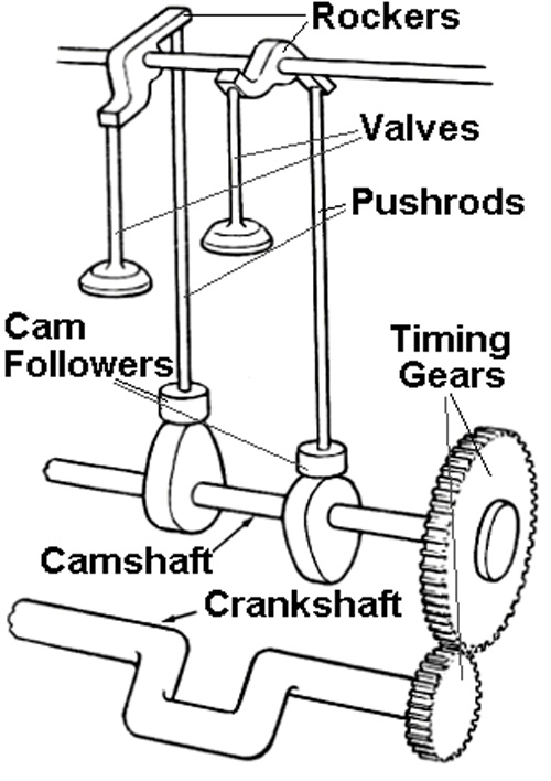
Figure 2 Typical internal components of an engine
In Figure 1 and 2 the crankshaft turns in main bearings. The piston, which is connected to the crankshaft by means of a connecting rod, moves up and down in the cylinder as the crankshaft turns. With the piston as low as it will go in the cylinder, it is said to be at bottom dead centre (bdc). When it is as high as it will go in the cylinder, it is at top dead centre (tdc). The distance the piston moves from tdc to bdc is called the ‘stroke’ of the engine.
The turning crankshaft drives the camshaft by means of timing gears (or by sprockets and a chain). Oval ‘cams’ on the camshaft open the inlet and exhaust valves at the correct time by means of push-rods and rockers. (An inlet valve allows air or fuel/air mixture to be drawn into a cylinder ready for combustion, while an exhaust valve lets exhaust gas out of a cylinder. The arrangement of camshafts and valves can be very different for different engine designs.)
Most marine engines have several cylinders for more power and smoothness. (The cylinders are identified by numbering them in order, from the front of the crankshaft (inboard end) to the back (propeller shaft end).
Two-stroke and four-stroke engines
Diesel and petrol engines can be either ‘two-stroke’ or ‘four-stroke’ cycle designs:
In four-stroke engines, the four essential operations (induction compression, combustion and exhaust) occur one after the other, in four separate ‘strokes’ of the piston (down, up, down, up). The four-stroke cycle takes two complete turns (720° rotation) of the crankshaft.
In two-stroke engines, the four essential operations occur in two ‘strokes’ of the piston (down, up). The two-stroke cycle occurs in one complete turn (360° rotation) of the crankshaft. This means that a two-stroke engine has twice as many power strokes as a four-stroke engine at the same speed, so it may produce more power. However, there may be losses in fuel efficiency and reliability.
Firing Order
In engines with several cylinders, the cylinders are designed to fire one after the other, to increase the smooth delivery of power. They do not fire in consecutive order (1,2,3,4,5,6,7,8), as this would have the effect of twisting one end of the crankshaft while the other end tries to catch up. Instead, cylinders are designed to fire, first at one end of the engine, then at the other. In this way, the power thrust is more evenly balanced on each end of the crankshaft.
Typical firing orders for internal combustion engines are:
Four cylinder engines 1,3,4,2 (sometimes 1,2,4,3)
Six cylinder engines 1,5,3,6,2,4 (or 1,3,5,6,4,2)
Vee Eight cylinder engines 1,5,4,8,6,3,7,2 is most common
Principles of Marine Diesel Engines
Operation of Four-Stroke Marine Diesel Engines
There are many different designs for diesel four-stroke cycle engines. Each has it’s own special features and characteristics. However, the general operation of a diesel four-stroke cycle engine is outlined on the following pages.
Induction Stroke
When the piston is at about top dead centre (tdc), the inlet valve is opened by the cam on the camshaft as the crankshaft rotates, and the induction stroke begins.
As the crankshaft rotates, the piston goes down in the cylinder (as shown in the diagram).
Fresh air rushes into the cylinder through the inlet port and inlet valve, to fill the space left by the piston as it goes down. When the piston reaches about bottom dead centre (bdc), the inlet valve is closed, trapping the charge of fresh air. The induction stroke is then complete.
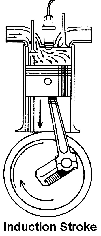
Figure 3 Induction stroke
Compression Stroke
At bdc, with both valves shut, the compression stroke begins.
As the crankshaft rotates, the piston moves up the cylinder toward tdc, and the air trapped in the cylinder is compressed (to about 5% of its normal volume) by the rising piston.
The compression of the charge of air heats it up to about 500°C, ready for the power stroke.
Most of us have felt this effect! Have you ever felt a pump get hot as you pumped up a tyre?
How hot is 500°C ? (Pretty Hot! Steel heated to about 600°C would be just starting to glow!)
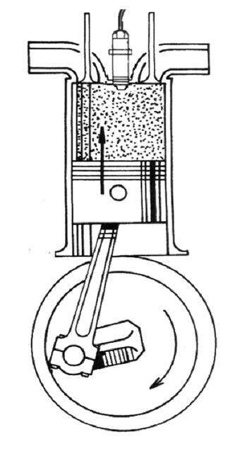
Figure 4 Compression stroke
At about tdc, the compression stroke is complete.
Combustion or ‘Power’ Stroke
Just before tdc, with both valves shut and hot compressed air trapped in the cylinder, the combustion or ‘power’ stroke begins......
An ‘injector pump’ which is driven by the camshaft, forces a small measure of diesel fuel into the cylinder at high pressure, through an ‘injector’. The injector breaks the fuel up into a fine mist which mixes with the hot compressed air, causing it to burst into flames (ignite).
As the piston passes tdc, the burning gas expands, driving the piston toward bdc. This rotates the crankshaft and drives the flywheel (and the load).
The mass (weight) of the flywheel is very important! The energy contained in the heavy rotating flywheel will keep the engine rotating smoothly until the next power stroke.
At about bdc, the power stroke ends.
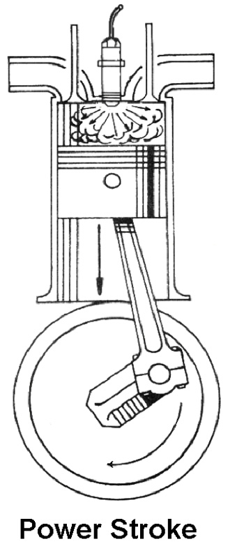
Figure 5 Compression stroke
Exhaust Stroke
Just before the piston reaches bdc, the exhaust stroke begins.
The exhaust valve is opened by a cam on the camshaft, and the pressure of the burnt gases is released into the exhaust.
As the piston reaches bdc and begins to rise, the piston pushes all the remaining burnt gases out of the cylinder through the exhaust valve.
As the piston reaches tdc, the exhaust valve is closed, and the exhaust stroke is complete.
At this point, the inlet valve is opened by it’s cam, ready for the induction stroke of the next four-stroke ‘cycle’.
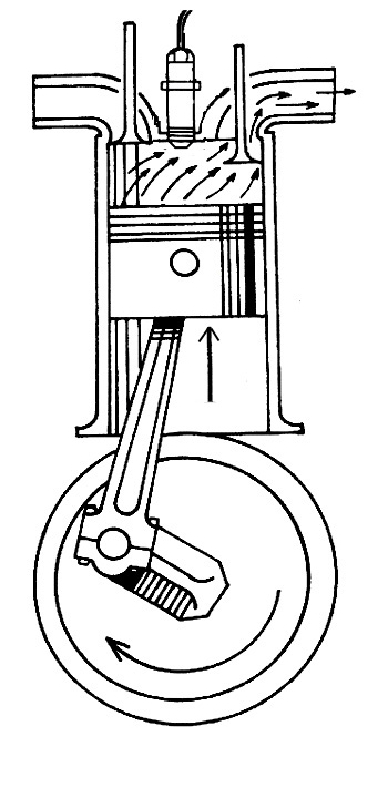
Figure 6 Exhaust stroke
Operation of Two-Stroke Diesel Engines
There are many different designs for diesel two-stroke cycle engines, and each has it’s own special features and characteristics. However, the general operation of a diesel two-stroke cycle engine is outlined on the following pages.
Stroke 1 - Upward
Exhaust and Induction of Fresh Air.
With the piston approaching bdc, the exhaust valve is opened by its cam. (Some engines have multiple exhaust valves to let burned gases out more quickly.) The pressure of combustion is released into the exhaust.
The inlet ‘ports’ which are machined through the bottom of the cylinder wall, are then uncovered by the piston.
Pressure from a ‘blower’ forces fresh air into the cylinder through the inlet ports, and drives the burnt gases out of the cylinder through the exhaust valves.
As the piston begins to rise, first the exhaust valves are closed, then the inlet ports are covered by the piston, locking in the charge of fresh air.
Exhaust and Induction are now complete.

Figure
7 Exhaust & Induction of Fresh Air
Stroke 1 - Upward
Completed exhaust stroke and compression stroke.
The piston continues to rise in the cylinder. This compresses the trapped air, and makes it hot.
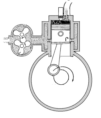
Figure 8 Compression almost complete
Injection and Start of Power Stroke.
Just before tdc as compression is completed, a measured quantity of fuel is injected into the hot compressed air, and it ignites.
Stroke 2 - Downward
Power Stroke.
After injection, the expanding burning gas drives the piston down the cylinder on the power stroke, turning the crankshaft and flywheel.
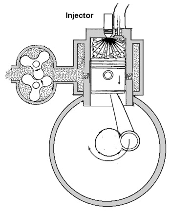
Figure 9 Injection and power stroke
Start of Exhaust and Induction.
Before the piston reaches bdc, the exhaust valves are opened by gears and cams to release the burnt gases into the exhaust.
The inlet ports are then uncovered by the descending piston as it approaches bdc. Fresh air is forced into the cylinder to replace the burnt gases. As the piston passes bdc, the next two-stroke cycle begins.
Scavenging
Scavenging is the name given to removing all the burnt gases from the cylinder.
Burnt gases left in the cylinder will reduce the power and efficiency of the engine.
Two-stroke engines do not use the piston to force burned gas from the cylinder, but rely on the incoming air to push it out.
Improving the airflow through the engine with a blower, and careful airflow design, improves scavenging.
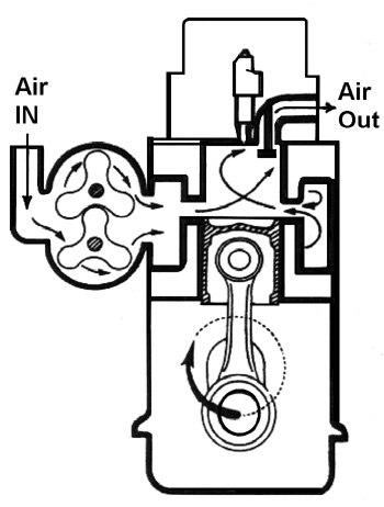
Figure 10 ‘Scavenging’
‘Blowers’ and ‘Intercoolers’
Blowers force air into the engine on the induction stroke for better ‘breathing’. They increase the power and efficiency of the engine, and also help to cool two-stroke engines, which tend to run hotter than four-strokes.
Blowers may be ‘superchargers’ or ‘turbo-chargers’.
Superchargers are driven directly by the engine. They are geared up to spin at 1½ to 2 times the engine speed (perhaps up to about 8000 r.p.m.)
Turbochargers are driven by a turbine which is powered by the engine exhaust. Some turbochargers may spin at up to 100,000 r.p.m. Balance and lubrication is critical under these conditions.
At high throttle settings, turbo vanes reach high temperatures in the blast of flame from the exhaust. If the engine is instantly shut down from high speed operation, this heat from the turbo vanes will ‘soak’ into the bearings and lubricating oil. The bearings may be damaged, and the oil burned by this heat. Due to its speed, the turbo might also ‘run-on’ for a substantial time after the engine lubricating system has stopped. This may also cause damage. To prevent these problems, hot engines should be allowed to idle for about 10 to 15 minutes before they are switched off, to allow the engine and turbo to cool down.
Blowers tend to heat the air by compression. ‘Intercoolers’ may be used to cool the air from the blower before it enters the engine. This increases the efficiency, and allows the engine to run cooler.
Timing of Valves and Injection
Valve and injection timing will vary widely for different engine designs, but both must be set exactly for any engine–even a small timing error can stop the engine, perhaps even seriously damage it.
Injection, and the opening and closing of the valves, is accurately timed in relation to the position of the piston, by the gear or chain drive from the crankshaft to the camshaft. The meshed teeth of the gears ensure that injection and valve operations occur at the correct point of each ‘cycle’.
In a four-stroke engine, there are twice as many teeth on the camshaft gear (or sprocket) as there are on the crankshaft gear. This means the camshaft runs at half the speed of the crankshaft. The camshaft turns (injection and valves operate) only once for every two revolutions of the crankshaft.
In two-stroke engines, injection occurs and the valves will open and close on each turn of the crankshaft. In two-stroke engines, the camshaft must run at the same speed as the crankshaft.
Petrol Engines
Petrol engines (mainly ‘outboards’), are often used in recreational boats, but are also used in specific purpose commercial vessels, tenders etc. Petrol ‘inboard’ engines are rarely used, except for recreational vessels which may use ‘marinised’ car engines.
Operation of Four-stroke Cycle Petrol Engines
Four-stroke cycle petrol engines are similar in operation to four-stroke diesel engines, with some differences.
Four-stroke petrol engines have the following major differences to diesels:
Induction Stroke: In most petrol engines, fuel is mixed with air in a ‘carburettor’. The fuel/air mixture is drawn into the cylinder during induction, instead of pure air. Some petrol engines may use injection, however.
Power Stroke: At the start of the power stroke, the petrol/air mix is ignited by means of an electrical ‘ignition’ system and a ‘spark plug’, instead of the heat of compression. (The compression ratio of petrol engines is lower than diesel engines.)
The timing of the spark ignition for four-stroke petrol engines is normally taken off the camshaft.
The operating strokes of a four-stroke petrol engine can be outlined as:
Induction Stroke Piston going down in cylinder, inlet valve open. Fuel/air mixture is drawn into the cylinder.
Compression Stroke Piston rising toward tdc, both valves shut. Fuel/air mixture is compressed in the cylinder.
Power Stroke Electrical ignition system causes an electrical spark to jump the gap between the spark plug electrodes. The spark ignites the compressed fuel/air mixture. The piston is driven down by the expanding gases.
Exhaust Stroke Piston Rising, exhaust valve open. The burnt gases are driven into the exhaust by the rising piston.
Operation of Two-stroke Cycle Petrol Engines
Two-stroke engines are often used for outboard engines, and may be used for small auxiliary engines (pumps, generators etc).
Instead of conventional valves, two-stroke petrol engines most often use ‘ports’ cut into the cylinder wall. These are opened and closed by the piston as it moves up and down inside the cylinder.
The crankcase is normally used as part of the fuel path. A two-stroke petrol engine is usually lubricated by adding two-stroke oil to the fuel (petroil mix). Alternatively, an oil injection system may inject oil into the engine at pressure. (This system does not re-use the oil–an oil supply tank is regularly topped up.)
Upward Stroke
Compression stroke & Induction of fuel/air into the crankcase
The piston rising from bdc, covers the transfer and exhaust ports in the cylinder wall, and then uncovers the intake port into the crankcase. (Figure 10)
The trapped fuel/air mixture is compressed in the top of the cylinder (Compression)
At the same time, the rising piston creates suction in the crankcase. This suction draws fuel/air mixture from the carburettor, through the intake port, to fill the crankcase. (Induction into crankcase).
Figure 11 Compression and Induction into crankcase
Downward Stroke
Power stroke & compression of fuel/air in the crankcase
As the piston reaches tdc, the spark ignites the fuel/air mixture forcing the piston down on the power stroke. (Combustion)
The descending piston closes the intake port, and then compresses the fuel/air mixture trapped in the crankcase. (Figure 11)

Figure 12 Power stroke
Downward Stroke
Exhaust stroke and transfer of fuel/air mix into the cylinder
When the piston approaches bdc, it uncovers the exhaust port in the cylinder wall, allowing the burned gases to escape through the exhaust port. (Figure 13)
Shortly after, the transfer port in the cylinder wall is uncovered, and the compressed fuel/air in the crankcase rushes through the transfer port into the cylinder (Induction stroke and scavenging). (Figure 13)
Figure 13 Bottom dead centre Induction stroke and scavenging
The shape of the engine components (combustion chamber, ports, and piston crown) are designed so the incoming fuel/air charge drives out any remaining burned gases without too much of the fresh charge escaping through the exhaust port. (Figure 13)
Many different port, combustion chamber, and piston designs have been used by different manufacturers to try to improve scavenging, engine efficiency, and power.
To improve the induction of fuel/air mixture into the crankcase, one-way valves (check valves, reed valves, or rotary valves) may be used in the intake port. These allow the fuel air charge to get into the crankcase quickly, but prevent it leaking back out.
Petrol two-stroke engines are simple, and powerful for their light weight, but they are normally less efficient and less reliable than either four-strokes or diesel two-strokes.
Reversing Gearboxes
Smaller commercial vessels are normally equipped with a ‘Thrust Reversing Gearbox’ which has three gear positions–‘Ahead’, ‘Neutral’, and ‘Astern’.
This allows the vessel to navigate and maneuver safely.
An example of a typical thrust reversing gearbox is shown in Figure 14
.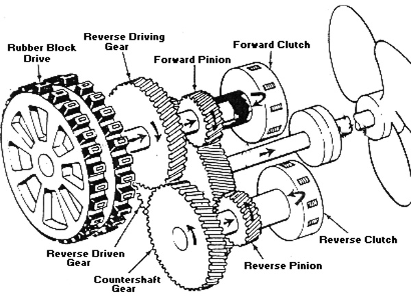
Figure 14 ‘Marine Gear’, thrust reversing Gearbox
Reduction gear-sets are often included in a gearbox to match the engine and propeller speed ranges.
With different gearboxes, the gears may be changed:
· mechanically, using the movement of the gear lever to change the gears, either directly, or through a cable or linkage.
· electro-mechanically, using a switch to operate electrical solenoids which change the gears
· hydraulically, using mechanical clutches operated hydraulically, or by using gearboxes with hydraulic operation (more like car automatic gearboxes).
Oil levels in gearboxes must be regularly checked according to the maintenance schedule.
The gearbox control and engine throttle (speed) may use separate levers for thrust and speed, or be combined in a single control lever (see Figure 15).

Stern Tubes
The stern tube contains the propeller shaft, and shaft bearings and seals. The stern tube may be water lubricated, or oil-filled.
With water lubricated stern tubes (Figure 16), the stern tube fills with sea water, and the shaft runs in water lubricated bushes.
A gland at the inboard end stops too much sea-water leaking into the vessel, but some weepage is acceptable as this helps to lubricate the gland. The gland can be periodically checked and tightened slightly to reduce weepage if
necessary, and re-packed as the packing material wears away.
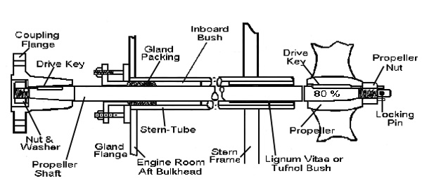
Figure 16 Water lubricated stern tube
Oil-filled stern tubes (Figure 17) give better lubrication and reduce corrosion. Sea-water is kept out of the stern tube by an outboard seal. An inboard seal holds oil inside the stern tube to lubricate the bearings. The stern tube oil header tank should be regularly checked and topped up.
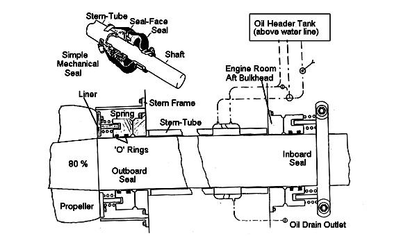
Figure 17 Oil-filled stern tube
The propeller shaft must be correctly lined up with the gearbox shaft. Misalignment will cause noise and vibration while the shaft is running. Gearbox and shaft bearings will overheat and collapse more quickly.
Outboard engines have a sealed, oil filled ‘foot’ containing gearbox, bearings, shafts and seals. The oil level in the foot should be regularly checked and periodically changed as shown in the engine maintenance schedule.
The ‘engine cooling system’ is really a ‘temperature control system’. It keeps the engine temperature within the best operating range, at all speeds and under all load conditions. It should not keep the engine cold.
Engine cooling systems may use air or liquid coolant to take heat from the engine.
Air Cooling
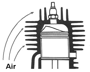
Figure 18 Air Cooling
Air cooling (Figure 18) is seldom used for marine engines, but may be used on auxiliary engines.
A fan on the engine shaft, blows air past ‘cooling fins’ on the engine castings. Metal cowling concentrates the air flow where it is most effective for removing heat.
Maintenance is reduced to keeping air cowls and cooling fins free of dust and rubbish.
Air cooled engines should be operated in open, well ventilated areas.
Liquid Cooling (Water Cooling)
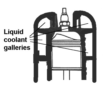
Figure 19 Liquid Cooling
Liquid cooling (Figure 19) is usually called water cooling, but due to the rust and corrosion caused by water, other liquids are often used.
Liquid coolants pass through special water ‘galleries’ in the engine castings, to cool the engine.
Liquid cooling systems often consist of:
· Pump/s to push the coolant through the system
· Engine coolant galleries
· Thermostat to allow a cold engine to quickly reach operating temperatures
· A cooling device may be used to cool down the hot coolant
Several different types of liquid cooling systems are used (these are outlined on the following pages).
Direct or Raw Water Cooling
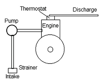
Figure 20 Raw Water Cooling
This is a simple method of liquid cooling. Raw (sea) water is pumped from outside the vessel, though the engine cooling system, and back out again (see Figure 20).
This method is normally used for outboard engines, but is seldom used for larger engines because of the corrosive nature of sea water. In outboards, the water pump is mounted in the drive foot of the engine.
Intake strainers must be regularly cleaned, and pump impellers will periodically need to be replaced.
Indirect or Closed Circuit Cooling
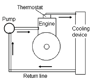
Figure 21 Closed Circuit Cooling
This method (Figure 21) is similar to automotive systems.
The coolant in the engine is pumped around and around through a cooling circuit, consisting of:
· a circulating pump
· the engine cooling galleries
· temperature regulating thermostat
· a device to take heat away from the coolant
The coolant takes the heat from the engine and carries it to a cooling device which removes heat from the coolant. The coolant then goes back to the engine to remove more heat.
In this system, only clean anti-corrosive coolant passes through the engine.
There
are several ways to remove heat from the coolant:
· Keel cooling. Piping carries the coolant through the hull and along underneath the vessel, then back to the engine. As the hot coolant passes through the pipe, it is cooled by the sea-water outside.
· Skin Tank cooling for metal vessels. A metal tank is formed against the bottom skin of the vessel. The coolant passes through the tank, and is cooled by the hull in the sea water.
· Keel and skin tank systems are both fully closed. There are no sea water strainers to block, but marine growth on the outside of the keel pipes and hull reduces the effectiveness of both systems.
·
Heat Exchanger cooling (see Figure 22). Hot coolant flows in a closed circuit
from the engine, through the cooling tubes inside a heat exchanger, and back
to the engine. Raw sea water is pumped from outside the vessel via a separate
system, and through the heat exchanger to cool the coolant. The raw water
then returns to the sea.
This system needs two separate pumps–one for the coolant, and one for raw
sea-water. This system is not affected by marine growth, but the raw water
system and strainer must be kept clean.
The raw water flows through the cooling tubes in the top section.

Figure 22 Heat Exchanger cooling system
The heat exchanger in Figure 23 is designed to remove heat from the coolant and from the engine lubricating oil.
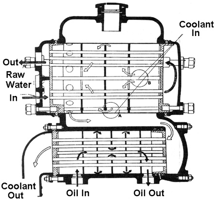
Figure 23 Heat Exchanger
Hot coolant flows into the top section, and around the cooling tubes where heat is removed by the raw water. The (cooled) coolant then flows down through the tubes in the bottom section and back out to the engine.
Engine lubricating oil flows around the tubes in the bottom section, and is cooled by the coolant on its way through the heat exchanger.
The oil retains some warmth as cold raw water is not
used to cool it.
Like automotive systems, indirect or closed marine cooling systems may operate under pressure.
If you remove the pressure cap while the engine is hot, the drop in pressure in the cooling system can instantly boil the coolant and spray boiling liquid over you.
Do not remove the pressure cap while the engine is hot!
‘Thermostat’ for Temperature Regulation
In direct cooling systems, the thermostat (Figure 24) will reduce–but not stop–the flow of water while the engine is cold. This allows the engine to warm up quicker.
In indirect or closed systems, the thermostat bypasses the heat exchanger, so the coolant only circulates through the engine. When the engine is warm, the thermostat closes the bypass, and sends the coolant to the heat exchanger.
All systems must keep some coolant flowing through the engine, so it does not boil and cause local hot spots in the engine.
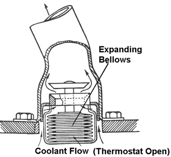
Figure 24 Thermostat
Several different types of thermostats are made, using:
· Wax Elements
· Bellows
· Bi-metal springs
All of them operate in a similar way, but it is essential that exactly the right type be fitted to the engine, to prevent temperature problems.
Occasionally a thermostat will stick. A sticking thermostat may cause the engine to take too long to warm up, or it may cause overheating.
Where the engine is overheating while under way, a stuck thermostat can be temporarily removed (after the engine cools down), to get you back home.
Either way, the sticking thermostat must be changed for the correct replacement as soon as possible.
Water Circulating Pumps
Water pumps may be positive displacement pumps, or non-positive pumps.
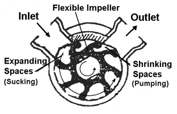
Figure 25 Positive Flexible Impeller Pump
Positive pumps work on the principle of spaces between the vanes expanding at the input (so they suck in liquid), and shrinking at the output (so they force the liquid out). Flexible rubber impellers are one way of doing this (Figure 25).
Non-positive pumps use a simple vaned impeller spinning at high speed.
Water is drawn in at the centre and flung around to the outlet by centrifugal force. Non-positive pumps must be almost full of water to allow them to pump.
Pumps may use mechanical seals or packing to minimise leakage.
The sea water inlet to cooling systems includes a sea-cock to close the inlet and a strainer and weed-trap. These must be regularly checked and cleaned.
Cooling system pumps should not be run dry as this may damage impellers and/or seals.
Some flexible impeller pumps may also be damaged by turning them backwards, as this tends to turn the vanes ‘inside out’, cracking the rubber.
Temperature Indicators
Temperature gauges or warning lights may be used for engine coolant temperature, engine oil temperature, transmission oil temperature, even hydraulic oil temperature.
Temperature gauges and warning lights may be operated:
· mechanically using a ‘Bourdon’ tube. (A coiled ‘Bourdon’ tube unrolls and turns a gauge pointer as it heats up.)
· electrically using electrical ‘sender’ units. Senders may:
- vary the current through an electrical gauge
- have a switch which operates at a critical temperature to light
a warning light
Lubricating oil has three main functions:
· it keeps working surfaces apart to minimise friction and heat under conditions of temperature, pressure, and contamination
· it helps to carry heat, grit and contaminants away from machine surfaces
· it increases the seal between moving components (for example, piston to cylinder gas seal, which is needed to maintain compression).
Force Feed Systems
Except for petrol two-strokes, and small four-stroke auxiliary engines, most marine engines use a ‘force feed’ lubrication system (Figure 23). Typical components of a force feed system are:
· oil supply tank or sump
· oil pump
· oil filter
· oil galleries feeding critical engine components
· oil cooler
· pressure and temperature gauges, if required.
In the force feed lubrication system, oil is pumped from a sump or tank, filtered, and supplied under pressure through oil galleries to critical components (bearings, etc.) of the engine. Less critical parts of the engine (gears, chains, etc.) are lubricated by oil splashed from bearings and other oil fed parts.
The used oil drains into the sump of the engine, where it is returned to the oil pump or supply tank, to be used over and over again.
Most force feed systems have the oil reserve stored in the sump of the engine (like car engines). These are called ‘wet-sump’ lubrication systems. Others have the oil reserve stored in an external supply tank. These are called ‘dry-sump’ systems
The system in Figure 26 uses a ‘wet sump’. The oil supply is stored in the sump below the engine. A pump in the sump circulates the oil to the engine. After lubricating the engine, used oil drains back to the sump to be constantly re-circulated through the engine.

Figure 26 Wet sump system
Figure 27 shows a ‘dry sump’ system— oil is returned to the external oil tank by a scavenge pump. The scavenge pump is larger than the delivery pump to stop oil ‘pooling’ in the sump. Dry sump systems have larger oil tank capacity, and are more reliable in heavy seas. The oil also remains cooler, and is less likely to leak past engine seals.
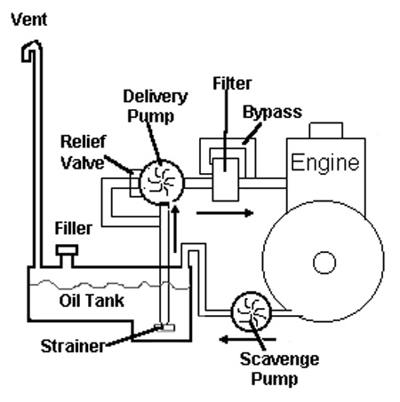
Figure 27 Dry sump system
The oil delivery pump can develop extremely high pressures.
A relief valve on the oil pump will open to limit the oil pressure,
to prevent damage to the engine.
If the oil filter blocked up, no oil would get to the engine. The bypass
valve will let unfiltered oil past a blocked filter to supply the engine.
(Slightly dirty oil will do less damage than no oil at all.)
Acids and contaminants build up in the oil. Always replace the oil and filters when indicated by the service schedule, or earlier if they need it.
Use the correct type and grade of lubricant, and never mix them. Oils and greases with different chemical bases may interact and cause expensive damage.
Lubrication of Two-Stroke Engines
Diesel two-stroke engines normally have a conventional ‘wet-sump’ force feed system as just described.
Most two-stroke petrol engines are lubricated by ‘petroil’ or ‘outboard’ mix as it passes through the crankcase during induction. To ensure proper lubrication, and to prevent starting and running problems, you must make sure that:
· only the correct type of two-stroke oil is used
· the correct quantity of oil is added to the petrol
· the petrol and oil are thoroughly mixed together before being used
A few high performance two-strokes, force feed a small amount of undiluted oil directly into the bearings and critical components from an oil supply tank. This is called ‘oil injection’. The used lubricating oil is eventually burned with the fuel, and the oil tank must be occasionally topped up to replace the lost oil.
Straight petrol is used with oil-injected two-strokes.
Diesel Fuel Systems

Figure 28 Diesel fuel system
Typical components of a marine diesel fuel system are shown in Figure 28.
Explanations:
Main
Tank/s. Mounted
low in the vessel– high tanks may affect vessel stability. Emergency
shut-off valve to allow the fuel supply to be cut off outside the engine room,
in the event of emergency. Vent pipe (high) with a flash trap allows the tank
to ‘breathe’. Drain tap allows water and sludge to be drained from the tank.
Filters may be fitted in the filler neck and fuel pipe. Standard
filler coupling, filling line and valve to allow tank to be filled safely.
Fuel gauge may be fitted, but sounding rods are more reliable and accurate.
Service tanks with sludge drain valve and low fuel
level alarm may be fitted .
Filters. The primary filter (sludge trap) settles out water and sediment. It may be periodically drained (into a container). The secondary fuel filter is a fine element type filter which must be changed according to service schedule.
Pumps. The fuel lift pump may be an engine driven mechanical pump or an electric pump to lift fuel at low pressure from the tank to the injector pump. The hand priming pump allows the injector pump to be primed, and ‘bleeding’ of the fuel system if necessary. The injector pump is timed to inject a squirt of fuel into each cylinder at the correct moment for combustion. Injector pump timing is critical, and must be set by an expert.
Injectors. Deliver the fuel as a flammable mist into the cylinders at the moment of injection. Spray patterns for typical good and faulty injectors, are shown in Figure 29 and 30.
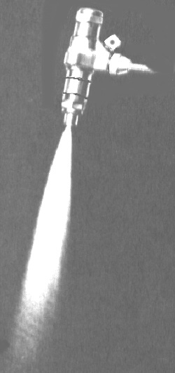
Figure 29 Good Injector - Full Spray Pattern
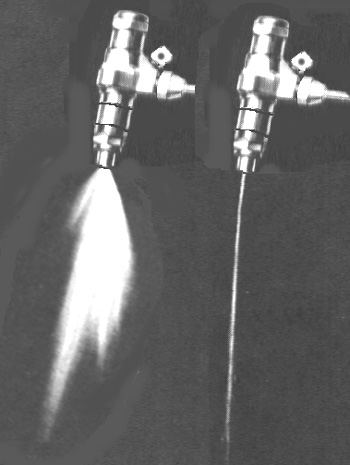
Figure 30 Faulty Injectors - Deflected Spray Pattern, and Non-atomised Stream
Faulty injectors will often cause starting problems, poor performance, black exhaust smoke, and unburned oil as droplets in the exhaust.
Fuel Lift Pump
A mechanical diaphragm fuel pump is outlined in Figure 30. The pump rocker arm is driven by a cam on the cam shaft.
As the diaphragm is pulled out by the rocker arm, fuel is sucked into the pump body.
Pressure from the diaphragm spring pushes the diaphragm back to deliver fuel to the outlet.
If no fuel is needed, the diaphragm can’t go back, and the pump simply ‘idles’ without delivering fuel.
Electrical pumps may use a similar pump mechanism, operated by an electric solenoid.
Types of Diesel Fuel Injection Systems
There are as many types of injection systems as there are engines. The types are summarised below:
Element type fuel systems –
The injector pump has a separate high pressure pump element for each injector, each appropriately timed for injection.
Distributor type fuel systems –
A single high pressure injector pump has a ‘distributor’, to direct the fuel stream to each of the firing injectors in turn.
P.T. type fuel systems - Each injector includes its own injector pump and fuel metering system. The pump/injector units may be driven directly from a cam on the camshaft.
Injector pumps are normally operated from the camshaft, because they must be timed for correct ignition. The ignition pump also includes:
· a throttle mechanism to precisely set the amount of fuel delivered by the pump to the injectors
· a governor to keep the engine speed at the throttle setting, regardless of load
· a fuel cut-off mechanism to stop the engine when required.
Caution! Water in the fuel can damage the injector pump. Keep fuel and filters clean!
The hydraulic pressure at the injectors and injector pump can penetrate your skin, and damage your eyes. Beware of injector pressure!
Bleeding of Diesel Fuel Injection Systems
Diesel fuel systems rely on the fact that fuel cannot be compressed. An injector pump may apply thousands of kPa pressure to the diesel fuel to force it through an injector into the cylinder. If any air is allowed into the system, it will be compressed during injection, and will prevent proper injection. Air must be completely removed from the fuel system using a point-to-point (tank through to injector) bleeding process.
Petrol Fuel Systems
Petrol fuel systems use similar tank, filter, and pump arrangements to the diesel system in Figure 28, but instead of the injector pump and injectors, petrol will be atomised and mixed with air in a ‘carburettor’. The fuel /air is then supplied to the cylinders through an intake manifold. The carburettor will regulate the amount of air/ fuel supplied to the engine at different speeds, and can increase the amount of petrol (make the petrol/air mix ‘richer’) to make cold starts easier. This is called ’choking’ the engine.
Most carburettors have the following main components:
· A float bowl, float and needle valve, keeps a constant petrol level in the float bowl. The fuel pump delivers fuel through the needle valve. As the level in the bowl rises, the float rises on top of the fuel, forcing the needle valve shut. This cuts off the flow of fuel into the bowl. If the level drops, the float will take pressure off the needle valve and let in more fuel. The float bowl also helps to trap sediment, to prevent it blocking the ‘jets’.
· Fine brass jets regulate the amount of fuel which is delivered into the air stream drawn through the throat of the carburettor on induction. Several jets may be provided for low speed, high speed, acceleration, etc.
· A butterfly valve in the main throat below the fuel venturi increases or decreases the flow of fuel/air to the engine (throttle).
· A butterfly valve above the venturi restricts the flow of air, without reducing the flow of fuel. This chokes the engine for cold starts.
Caution! Water in petrol will block the fine carburettor jets, and stop petrol getting through.the water is fresh, a small amount of methylated spirits in the tank might help to dilute the water and allow it to go through the jets. Salt water however, forms salt crystals which will block the jets. They will then have to be removed and cleaned before the engine can be started. Fuel filters will help to trap sediment and water before they enter the carburettor. Always keep the fuel system and filters clean!
Pre-start Checks & Preparing for Sea
When preparing for sea in vessels with inboard engines, the following checks should be carried out:
1.
Visually check the
engine, propulsion equipment, and bilge for:
- fuel, oil, water, or coolant leaks
- crushed or damaged hoses and pipes
- loose, broken, or damaged parts
These checks are usually done with engine and engine-room cleaning duties.
2. Check that the selected tank fuel cock is on.
3. Check that the battery master switch is on.
4. If necessary, check sea-water suction cock, strainers and weed traps.
5. Check and drain sludge filter, if appropriate.
6.
Check the level
and appearance of:
- coolant
- lubricating oil of engine and propulsion equipment
The appearance of coolant and lubricating oil may warn you of problems—oil
scum in the coolant, or water sludge in the lubricating oil or fuel, can all
mean trouble.
7. Where the bilge pump runs continuously, check this is on.
8. Follow the specified cold starting procedure to start the engine. Note any difficulties with starting the engine, as this indicates problems which need checking.
Operating Checks
After starting the engine:
1. Check engine oil pressure. Make sure it is normal.
2. Check engine water temperature. Make sure it is normal.
3. Check lubricating oil temperatures (where appropriate). Make sure they are normal.
4. Make sure the generator/alternator is charging.
5. Make sure alarms are switched on.
After leaving the wharf, regularly check:
1. Check engine water temperature. Make sure it is normal.
2. Check engine oil temperature. Make sure it is normal.
3. Make sure the generator/alternator is charging.
4. Check the engine for fuel or water leaks, and loose or damaged parts.
5. Check that the stern gland is not heating or leaking too much.
6. Check the raw water discharge or tell-tale for water flow, if necessary.
7. Check for the sound of the engine and propulsion equipment. Rough running, excessive vibration, and unusual mechanical noises may indicate problems, and must be investigated. Check for even, steady power from the engine, with no surging, hesitation, or flatness.
8.
Check the exhaust:
- Black smoke or puffs from diesel exhaust indicate faulty injector/s or general
problems with injection equipment.
- Black smoke from petrol engines indicate the engine is running rich (too
much petrol used).
- Blue smoke with lube oil shows faulty piston rings.
- White smoke from a diesel shows poor compression, but some smoke will often
show before the engine warms up.
- Unusual exhaust ‘beats’ may also need investigation.
Checks On Shut-down
Let the engine idle for some time to cool-down, particularly with turbo-diesels.
1. Perform operating checks during the cool-down period.
2. Follow the specified engine shut-down procedure.
3. Turn the fuel tank cock off.
4. Turn the sea-water suction cock off.
5. Turn the battery master switch off, if appropriate.
6. Turn the bilge pump off, if appropriate.
A failure of ship's machinery can involve a lot of risk, especially in bad seas, or dangerous waters. Saving money by reducing maintenance can result in heavy losses. Correctly following the maintenance schedules can reduce the risk of machinery stoppages, and reduce the cost of repairs when they are needed.
Some critical maintenance items on the Service Schedule for inboard engines and propulsion equipment are:
· Cleaning and/or replacing air, fuel, and oil filters as per schedule.
· Checking and changing lubricating oils in engines and gearboxes.
· Lubricating machinery.
· Checking/tightening vee belts.
· Checking pump impellers and seals.
· Checking injectors and valve adjustments.
The maintenance schedule shows the maximum engine running time between carrying out these jobs, but they should be done more often if necessary.
Outboard Engine Maintenance & Preparing for Sea
If correct care and maintenance has been properly carried out, modern outboards are normally reliable, and preparing for sea with an outboard engine is simple. After the vessel is launched:
· Make sure the engine is tilted into the water, and the gears are in Neutral.
· Connect fuel lines from a tank containing fresh fuel of the correct mixture.
· Turn on fuel taps, open tank vent, and prime engine with fuel using the primer bulb if necessary. Check the emergency stop switch or lanyard is set in the Run position.
· Follow the engine starting and warm-up procedure from the handbook.
·
Check cooling water
‘tell-tales’ to ensure the cooling system is working.
(If the engine has a ‘thermostat’, ‘tell-tale’ flow may be delayed for 45
seconds. Take care, as a cooling system failure may destroy the engine.
· Reduce engine to normal idle speed before engaging gears.
Modern outboards need less maintenance than earlier outboards. Electronic ignition systems and fixed fuel jets are often used, and these need less regular attention. However, regular maintenance is essential for maximum life and reliability.
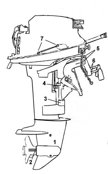
Figure
31 Example of Lubrication Points on a ‘Mercury’ outboard
Maintenance must be carried out according to the manufacturer’s handbooks, but normally includes:
Regular Inspections
· Clean the engine with a rust preventative and inspect for loose, damaged or missing parts.
· Check fuel lines for cracks or damage, and clean or replace fuel filters.
· Check spark plug wires and electrical wiring for cracks in the insulation or corroded terminals.
· Check propeller for nicks, bends or cracks. Check the drive bush or pin.
· Inspect the anodic plate and replace if it is badly eroded.
· Make sure the anodic plate is
not missing, painted over, or coated in oil or grease.
· Whenever the engine is running, check that a good stream of water is flowing from the ‘telltale’. A reduced flow may show a blocked cooling system, or worn or damaged water pump–check it out immediately.
Lubrication
· Lubricate all pivots and linkages according to the engine handbook (See example in Fig 31)
·
Routinely check, drain and refill gearbox ‘foot’ with the correct
marine gear oil.
To prevent air locks, the gearbox is filled from the bottom with the top vent
plug removed. The gearbox is full when oil flows from the vent.
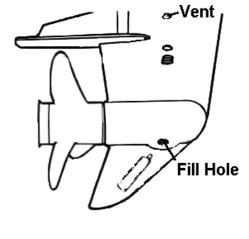
Figure 32: Replacing gear-oil in outboard ‘foot’
Note: When checking or re-filling the gearbox, the following conditions may mean trouble, and must be checked out:
- Water or milky brown oil in the foot
- Metal particles on the magnetic fill plug
- There is evidence that the gearbox oil level was very low
Ignition Systems
There is little maintenance either required or possible on electronic ignition systems. However, the spark plugs must be periodically cleaned or replaced to keep the engine starting and running well. The spark plug gaps must be set according to the manufacturer’s specifications before plugs are replaced in the engine. Any damaged plugs must be replaced. When replacing the spark plugs, screw them in by hand until finger-tight, then use a spark plug spanner to tighten them another ¼ turn to bed them against the gaskets. Do not over-tighten the spark plugs.
For earlier ‘magneto’ ignition systems, the magneto breaker points will need to be periodically checked and adjusted according to the manufacturer’s handbook.
Fuel Systems
Periodically clean or replace fuel filters according to the manufacturer’s handbooks.
Some engines may have fuel jets which are ‘screw adjustable’ to make the fuel/air mixture richer (more fuel) or leaner. Adjusting screws for Low Speed mixture and High Speed mixture may be provided. An Idle Speed adjustment is also often provided.
If adjustment to the mixture is needed, carefully follow the manufacturer’s handbook, as minor changes may cause starting and running problems.
Caution! Maintenance or repairs to an outboard motor are difficult, and almost impossible to carry out on a pitching vessel at sea. Ignition and fuel system repairs and adjustments are awkward, and are best done in a test tank on dry land.
If you make sure your outboards are properly checked and maintained, the risk of having to do repairs at sea is considerably reduced.
Flushing the Cooling System after using the Outboard
To prevent salt and/or silt build-up in the outboard cooling system, it should be periodically flushed with fresh water.
This may be done by placing the engine ‘foot’ in a large drum or tank. Fill the tank until the level of fresh water is well above the inlets, then run the engine in NEUTRAL for 3 to 5 minutes. This will pump water through the system and remove salt and silt deposits.
Alternatively, a garden hose attachment may be available to feed water directly into the engine water inlets. Make sure the water feed is adequate by turning the hose on until water escapes around the hose attachment.
Caution! An exposed spinning propeller is a hazard! While flushing the engine, leave it in Neutral, or remove the propeller from the shaft before starting.
To minimise the amount of work to correctly locate a fault on any type of marine engine, use the logical approach below:
1. Interpret the symptoms of the problem (black smoke - running roughly - won’t crank).
2. Decide what could be the general cause of the problem (fuel - air - electrical problem).
3. Decide which components might be causing the problem.
4. Carry out the simple elimination tasks before more involved work.
5. Decide whether the fault can be fixed by adjustment, or whether parts will need to be changed or repaired.
Troubleshooting Diesel Engines
On the next few pages are tables showing typical diesel engine problems, with their symptoms and corrective action.
Suggestions of how you can confirm the possible causes are also given.
| Starting Problems |
||
| Symptoms |
Possible Causes |
Corrective Action |
| Engine won’t crank |
Flat battery?–turn on work lights or other heavy current equipment. Do they work? |
Re-charge or switch to alternate battery |
| Engine won’t crank |
Loose battery terminals?–carefully check the battery terminals after an attempted start. Loose terminals may be hot |
Remove and clean terminals and battery posts, and replace |
| Engine won’t crank |
Faulty starter?–may be gummed up or worn brushes, or faulty drive mechanism. For an emergency start, try solidly tapping the starter, and/or rotating the engine slightly by hand. |
Have the starter repaired |
| Engine won’t crank |
Water in a cylinder through a faulty gasket? –water cannot be compressed so the engine locks on the compression stroke. Can the engine be turned by hand? Can the engine be turned backwards? |
Major engine repairs |
| Engine cranks but won’t start |
Fuel supply problems?–check fuel level and appearance, fuel cock, blocked fuel filters, loose or split fuel lines, and fuel pump |
Correct the problem |
| Engine cranks but won’t start |
Water in fuel?–check drain valves |
Drain, flush system. Refill and bleed |
| Engine cranks but won’t start |
Air filter blocked?–check and clean or replace |
Clean or replace filter |
| Engine cranks but won’t start |
Starting aids (when fitted) not operating properly?– glow plugs or other starting aids may be faulty. This may show up as the engine getting harder to start over time |
Check and replace aids |
| Engine cranks but won’t start |
Reduced compression?– in older engines and those left standing for a long time. Does the engine spin too freely on cranking? Can you detect compression strokes of all cylinders? |
Major Repair |
| Engine starts but misfires |
Faulty injection system?–check for leaks, loose connections or damaged pipes. |
Major Repair |
| Engine starts but misfires |
Uneven compression due to leaking gaskets or incorrect valve adjustments?–check the cooling system for bubbles and lubrication system for water. Note! Do not remove the pressure cap while the engine is hot! |
Major Repair |
| Cooling system problems |
||
| Symptoms |
Possible Causes |
Corrective Action |
| Engine overheating |
Blocked raw water system?–check raw water flow. |
Stop engine and check raw water intake, strainer, weed trap, raw water cock, and heat exchanger. |
| Engine overheating |
Pump problems?–visually check pumps for leaks and operation |
Repair |
| Engine overheating |
Coolant level low?–stop the engine and let it cool, then check levels. Find out what happened to the coolant. |
Repair and refill |
| Engine overheating |
Thermostat stuck?–identify by eliminating other things first |
May be temporarily removed to get you back home–but must be replaced |
| Engine takes a long time to warm up |
Thermostat stuck? |
Check and replace |
| Gauges read wrong |
Faulty ‘sender’ units? |
Check and replace |
| Lubrication Problems |
||
| Symptoms |
Possible Causes |
Corrective Action |
| Oil pressure low and possibly varying |
Oil level low, or oil too thin?–quickly stop engine, check oil and level, check for leaks, find out where the oil went |
Refill |
| Oil pressure low and possibly varying |
Oil pump intake pipes loose or fractured |
Check and repair |
| Low oil pressure |
Blocked filter (systems without bypass)?– quickly stop engine, check filter |
Replace |
| Low oil pressure |
Relief valve stuck open?–quickly stop engine |
Check and repair |
| Low oil pressure |
Pump problems? –quickly stop engine |
Check and repair |
| Low oil pressure |
Worn (run) bearings?–quickly stop engine. Was the engine making unusual knocking noises? |
Major repairs |
| High oil pressure |
Relief valve stuck closed, or oil too thick?–stop engine and check |
Check and repair |
| Fuel Problems |
||
| Symptoms |
Possible Causes |
Corrective Action |
| Fuel blockage |
Fuel level low? |
Check and refill. Bleed air from the system |
| Fuel blockage |
Water and sludge in system-Fuel filters blocked?–drain at tank and filters |
Drain, flush system. Replace filters, refill and bleed system |
| Fuel blockage |
Growths in fuel?–has the vessel had little use for a long time? Organisms grow in diesel oil unless it is constantly used and refilled. |
Drain and flush the entire fuel system. Replace all filters and bleed air. |
| Fuel not flowing |
Faulty fuel lift pump?–check flow from pump outlet when engine is cranked. Check lines and connections for splits and leaks, especially on pump suction side |
Repair or replace |
| Fuel not flowing |
Faulty injector pump?–firmly cover injector union with bunched cloth, loosen the union and crank engine. Check cloth to see if fuel was delivered to injector. Note! The hydraulic pressure form the injector pump may cause injury! Protect your skin and eyes |
Repair or replace |
| Engine Stops |
||
| Symptoms |
Possible Causes |
Corrective Action |
| Engine seized |
Undetected lubrication or cooling system problem?–are their signs of overheating? Can the engine be cranked? Check lube and cooling systems |
Repairs (possibly major) |
| Engines stops |
Fuel or air supply problems |
Check and fix as outlined earlier |
Troubleshooting Petrol Outboard Engines
Petrol engines are mainly use as two-stroke outboards. Most of the checks and test applying to outboards can also be applied to other petrol engines.
| Starting and Running Problems - Ignition |
||
| Symptoms |
Possible Causes |
Corrective Action |
| Engine won’t start |
Faulty spark plugs?–remove spark plug from engine. Check that the plug gap is clean and set correctly. Try replacing the plugs anyway, as they are the most common source of ignition problems |
Replace spark plugs |
| Engine won’t start or runs badly |
Faulty ignition system?–remove a spark plug. With
the wire attached to the spark plug, and the spark plug body touching
the engine, crank the engine and check for a spark at the plug gap.
The spark at the gap should be fat and strong. A thin weak spark shows
a faulty system. |
Clean and adjust magneto points or replace faulty components Electronic Ignition systems will normally need to be serviced or repaired at specialist workshops |
| Starting and Running Problems - Fuel |
||
| Symptoms |
Possible Causes |
Corrective Action |
| Engine won’t start |
Fuel supply problems?–Check fuel level, fuel cock, fuel lines and joins |
Refill or repair |
| Engine won’t start |
Stale fuel, too much oil in mix, or oil and petrol not properly mixed?–Petrol may not start an engine if it has been sitting for even one month. Always check that your two-stroke fuel is fresh, the correct mix, and well mixed before using it. |
Replace if you are not sure |
| Engine won’t start |
Engine flooded?–if the crankcase fills with excessive
fuel mix, the engine may not start. Remove and check a spark plug. If
it is very wet, the engine may be flooded with too much fuel. Open the
choke, turn the fuel off, and allow it to evaporate to dry the engine
out. Then try again. |
|
| Engine won’t start, runs badly, or stops |
Fuel blockage due to jets blocked by water or dirt?–remove and check spark plug, does it look moist or dry. A dry plug after several starting attempts may indicate blocked jets |
Clean and flush tank and fuel lines. Remove and clean carburettor bowl and jets |
| Engine won’t start, runs badly, or stops |
Mixture adjustments incorrect?–some carburettors have screw adjustable jets. If the adjustments are wrong, these symptoms will occur. Before fiddling around with a mixture adjustment, count how many turns it takes to screw the adjustment fully in. This will allow you to restore the original adjustment if necessary. |
Have the engine tuned up |
| Mechanical Problems |
||
| Symptoms |
Possible Causes |
Corrective Action |
| Poor starting |
Poor compression?–can you detect strong compression during cranking |
Major repairs |
| Cooling System Problems |
||
| Symptoms |
Possible Causes |
Corrective Action |
| Engine overheating |
Raw water intake blocked?– |
Check and clean |
| Engine overheating |
Water pump impeller worn?–check tell-tale stream from engine for strong, healthy flow |
Replace water pump impeller |
| Engine overheating or not warming properly |
Thermostat?–some outboards have thermostats to regulate the water flow. If these stick, they may cause these symptoms |
Replace |