AUXILIARY EQUIPMENT & SYSTEMS
FOR MARINE ENGINE DRIVERS
Ranger Hope ©
2008 View as a Pdf
file

This text is provided for research and study only on
the understanding that users exercise due care and do not neglect any
precaution which may be required by the ordinary practice of seamen or current
licensing legislation with respect to its use. No copying is permitted and no liability is accepted resulting from use.
AUXILIARY
EQUIPMENT & SYSTEMS
FOR MARINE
ENGINE DRIVERS
Ranger Hope ©
2008 View as a Pdf
file
Introduction
A well found vessel has equipment sufficient for the trade and seas that
she embarks upon. Modern engineering is
very reliable, often incorporating fail safe mechanisms and sophisticated non
serviceable components. Expert service engineers can be required to meet a
manufacturer’s warrantee. Licensed installers (LPG, electrical, and
refrigeration systems) may be required by National regulations. However, the
Marine Engineer remains on the spot, responsible to ensure that the vessel is
ready, and if systems fail, to repair them sufficient to reach a safe haven.
A basic understanding of maths and science, including calculation, how heat
and pressure change material, how forces stress materials and how momentum and
gravity affect motion will assist the reader. Engineers use these principles to
understand why machinery works and to interpret the signs and symptoms of
malfunction. Reference information can be found in the online dictionary at:
http://www.splashmaritime.com.au/Marops/Dictionary.htm.
The equipment and systems described may not be exactly match that fitted
on your vessel. Your manufacturer’s operating manuals must be consulted in
practical tasks. Ensuring a safe work practice and applying OH&S is
paramount. This includes using the correct tool for the job, use of personnel
protective equipment, (loose clothing can become entangled in moving parts) and
maintaining a tidy workplace.
Contents
1.1 The standards - Classification,
Marine Orders, USL Code, NSCV.
1.2 Survey - Initial, periodic, NSAMS
1.3
Safety Management - Risk analysis
Chapter 2:
Tanks and fluid management
2.1 Tanks - Fuel, water, ballast, sullage,
safety
2.2 Calculations - Tank capacity
2.3
Valves - Screw down, non return
2.4
Pumps - Positive displacement,
dynamic, gravity
2.5 Bilge systems - Survey, piping, operation, faults
Chapter 3:
Fire control systems
3.1 Principles of fire control - Fire triangle, transfer, classes, causes
3.2 Fire safety and survey - NSCV Part C Section 4, fire control
3.3 Fire detectors and alarms - Types, operation
3.4 Fire fighting equipment - Portable, extinguishers, fixed installations
3.5 Testing fire fighting equipment - Hoses, hydrants, shutdown, closures
Chapter 4: Deck gear and hydraulic systems
4.1 Steel wire rope, chain and breaking strain - Operation, splicing, strength
4.2 Blocks, purchases and tackles - Types, maintenance, rigs
4.3 Access - Stages, boson’s chair, rope ladders
4.4 Lifting gear
- Shackles, hooks, slings
4.5 Deck machinery - Winch, windlass, anchoring, safety, maintenance
4.6 Hydraulic power units - For winch application
5.1 Survey requirements - Performance, NSCV
5.2 Rudders - Passive, active
5.3 Steering systems - Direct drive, hydraulic, power assisted
5.4 Troubleshooting - Pre-departures, faults
Chapter 6: Gearing, shafting and propellers
6.1 Gears and
clutch mechanisms - Selection, clutches, torque converter
6.2 Reverse and reduction gear boxes - Operation, epicyclic, maintenance
6.3 Couplings and intermediate shaft
- Muffs, flange, flexible,
alignment
6.4
Stern tubes, shafts and alignment - Water, oil, mechanical, tailshafts
6.5
Propellers - Theory, calculations,
removal & fitting
Chapter 7: Marine DC electrical systems
7.1 Basic principles, units and simple circuits -Theory, series, parallel
7.2 The battery
- Lead acid, alkaline, installation, safety
7.3 Charging, generators and starter motor - Types, tests
7.4 DC circuit protection - Devices, shorts, stray current
Chapter
8: Marine AC electrical systems
8.1 Electrical safety with AC - DC, AC
8.2 Single and three phase - Wiring, transformers
8.3 AC circuit protection - Faults, isolation, earth, devices
8.4
The genset (engine driven alternator) - Distribution, shore power, calculations
8.5 Motor starter isolation and fuses - Decommissioning, systems
9.1 Principles of refrigeration -Terms, latent heat
9.2
The vapour compression refrigeration cycle - Operation, components, safety
9.3 Refrigerants - Regulations, types,
pressure
9.4 Common faults - Compressor, pressure
Chapter 10: Slipping, inspection and repair
10.1 Forces and stress - Hog, sag, rack, pant, point
10.2 Structures of a vessel
-Timber, steel, GRP
10.3 Materials and preservation - Attributes, deterioration, surface coatings
10.4 Slipping operations - Methods, preparation, checklist
10.5 Maintenance, inspection and repairs - Tests, tools, repairs, confined spaces
1.1 The standards
An historical perspective
To ensure safe vessels that would enjoy low insurance rates and higher resale value seafaring nations in the past developed Classification Societies to keep registers (lists of approved safe vessels). Those remaining today still determine rules (specifications) for construction, equipment and maintenance for each vessel class (the trade and sea area of operations).
American Bureau of Shipping
AB Det Norske Veritas NV
Lloyds Register of Shipping
LR Germanischer Lloyd GL
Bureau Veritas
For a new vessel, a
classification society such as those above will approve the design plans and check
the quality of materials and workmanship of all stages of the construction
process at what is called the Initial Survey.
Seafarers are additionally protected by their assignment of the vessel’s load
line to show minimum freeboard (preventing overloading) appropriate to the
intended sea area and by mandatory minimum safety equipment. To ensure maintenance
to the survey standards, regular ongoing thorough examinations are scheduled,
called Periodic Surveys.
Subsequently, concern
from nations that unregistered and unsafe foreign ships could sink in their home
waters, blocking their ports and polluting their seas resulted in forming the International Maritime Organisation as a
forum to promote sea safety. The IMO now encourages conformity in their
Conventions that include:
Safety of life at sea conference (SOLAS)
Loadlines conference (LOADLINES)
Marine pollution conference (MARPOL)
Standards of training and certification of
watchkeepers (STCW)
International Safety Management Code (ISM)
These conventions, the
World’s best practice, are supported
in domestic legislation in the jurisdictions of the Commonwealth of Australia
and its States and Territories.
Marine Orders and
Australian Maritime Regulations
The Commonwealth of
Australia’s jurisdiction operates to 200 nm offshore, the States’ to within 3nm
offshore, but extensions may cover zones of particular State interest. Where State
and Commonwealth Laws are incompatible, the latter can override. Like Class Societies, the Australian Maritime Safety Authority (AMSA) registers large vessels to Australian
standards, and the State Authorities
manage small vessels to their regulations.
Marine Orders are body of delegated legislation from the
Commonwealth Navigation Act 1912 and Protection of the Sea (Prevention of Pollution from
Ships) Act 1983 that update rules
for commercial vessel construction, operation and manning. They incorporate
reference to Australian Standards
(AS) for materials and components.
COLOURS OF
UTILITIES USED IN - AUSTRALIAN STANDARDS 2000 Water -
Emerald Green
Fire lines - Signal Red Steam - Silver Grey Air - Arctic Blue Oil -
Golden Brown
Gas - Light Beige Hazardous - Golden
Yellow Acids
/Alkalis- Violet (Services). Electricity - Light Orange Communications - White Other fluids, including drainage pipes, bilge lines
- Black
The examples below show
some of the Marine Orders of
particulars relevance to Marine Engineers for commercial vessel construction
and operations. The full list of Marine
Orders currently in force can be accessed at the AMSA website.
Marine Order 11 Substandard ships
Marine Order 12 Construction-Subdivision
& stability, machinery and electrical installations
Marine Order 14 Accommodation
Marine Order 15 Construction-fire protection, fire detection
and fire extinction
Marine Order 16 Load Lines
Marine Order 17 Liquefied gas carriers and chemical tankers
Marine Order 23 Equipment-Miscellaneous and Safety
Measurements,
Marine Order 25 Equipment - Life-saving
Marine Order 31 Ship surveys and certification
Marine Order 32 Cargo Handling Equipment
Marine Order 34 Solid bulk cargoes
Marine Order 41 Carriage of dangerous goods
Marine Order 42 Cargo stowage and securing
Marine Order 43 Cargo & Cargo Handling-Livestock
Marine Order 49 High Speed Craft
Marine Order 58 International Safety Management Code
Marine Order 91 Marine Pollution Prevention – Oil
Smaller vessel registration
and survey is devolved to the State Authorities, including:
South Australia SA
Northern
Territory NT
Australian Standards and the USL/NSCV are increasing maritime
uniformity nationwide and negotiations are ongoing to form a Single National
Jurisdiction for conformity in maritime standards and law enforcement.
The Uniform Shipping Laws Code (USL)
The geographic zones under
the authority of Australian States range from the balmy Tropics to the wind
swept Southern Ocean. Not surprisingly, locally focused State determined standards
were different, creating barriers for vessels trading inter-state.
The voluntary Uniform
Shipping Laws Code (USL) was devised to promote uniformity in commercial vessel
manning and construction regulations for small vessels (< 35 metres). Five of
the Codes’ eighteen Sections, directly affected the day-to-day operations of Marine Engineers,
specifically:
Section 1
- Definitions and General
requirements
Section 10 - Life Saving Appliances
Section 11 - Fire Appliances
Section 13 - Miscellaneous Equipment
Section 15 - Emergency Procedures
The Code lists the classes
of vessels and prescribed standards that shall
be met.
Class 1 – Passenger vessels (i.e. carrying
more than 12 passengers).
Class 2 – Non-passenger vessels (workboats of
12 or less passengers).
Class 3 – Registered commercial fishing
vessels (passengers not allowed).
Class 4 – Hire & drive vessels
Each class of
vessel includes an operational area as follows:
A – Unlimited seagoing
B – Offshore to 200 nautical miles
C – Offshore to 30 nautical miles
D – Sheltered smooth and partially smooth
waters (wave height <1.5 metres)
E – Sheltered smooth waters only (wave
height <0.5 metres)
From the 1990’s the
USL Code was incorporated into States’ regulations while accommodating existing
arrangements of vessels operating to earlier standards. Being voluntary it was
implemented more completely in some States than others. It continues to have a
profound influence on small vessel regulations and safety nationwide.
The USL code lists
prescribed standards. For every vessel class there is a tabulated specification
that “shall be met”. In some
operations (novel and fast craft), industry found it stifled the use of equivalent
or better modern technological innovations.
National Standards
for Commercial Vessels (NSCV)
A newer National Standards for Commercial Vessels
has been drafted. While drawing from the USL code, the NSCV updates and provides
the flexibility required by marine developers and operators. It retains a
prescriptive approach to compliance in its “deemed to satisfy” standards (standards
that shall be met) but also provides
a flexibility with performance based “equivalent
solutions” (that can be proven to be as effective as those deemed to satisfy).
The Standards, accessed at the AMSA website are:
Part A: Safety Obligations
Part B: General Requirements
Part C: Design & Construction
Section 1: Arrangement, Accommodation and Personal
Safety
Section 2: Watertight
and Weathertight Integrity
2a-Load Line
Vessels
2b-Non Load Line Vessels
Section 3: Construction
3a-General
3b-Design Loadings
3c-Aluminium
Construction
3d-FRP Construction
3e-Steel
Construction
3f-Timber
Construction
Section 4: Fire Safety
Section 5: Engineering
5a-Machinery
5b-Electrical
5c-LPG for Appliances
5d-LPG for Engines
Section 6: Stability
6a-General Requirements
6b-Intact Stability
6c-Buoyancy and Stability after Damage
Section 7: Equipment
7a-Safety Equipment
7b-Communication Equipment
7c-Navigation Equipment
7d-Anchoring and Mooring
Equipment
Part
D: Crew Competencies
Part
E: Operational Practices
Part
F: Special Vessels
Section 1: Fast Craft
1a-General
Requirements
1b-Category
F1 Fast Craft
1c-Category F2 Fast Craft
Section 2: Hire and
Drive
Section 3: Novel
Vessels
Section 4: Special
Purpose Vessels
Another difference
from the USL code is that the principles of risk management outlined in the
International Safety Management Code (ISM) are adopted by the NSCV (particularly
in Section 4, Fire Safety) where a risk factor based on vessels class and operations determines survey
requirements.
National Standards for the
Administration of Marine Safety (NSAMS)
These newest
Standards are intended to be applied through a single national jurisdiction
reform under Commonwealth legislation. It envisages a single national Authority
with multiple survey organisations that may be operated by private industry or
by State or Territory Government agencies. There are three possible models
specified in the Regulatory Impact Statement for National Approach to Maritime Safety Reform (NAMSR). No decision
had been taken about the service delivery model at the time of publication of
this standard.
1.2 Survey
This text primarily
refers to the standards of NSCV. Your commercial vessel may be in Class, AMSA
or State survey and you must consult their standards and rules to ensure survey
compliance. However, some general principles apply.
To approve a vessel
authorities and/or classification societies survey
their vessels (a thorough examination by a surveyor or approved person). Some
items may be just require inspection
(be visually checked by an approved person) or some may require a test (be subject to meeting a
performance criteria).
Initial survey and load lines
A vessel brought into
survey for the first time is required to undergo an initial survey to approve the plans and check that the quality of
materials/workmanship meets the safety parameters appropriate to the trade and
sea state (vessel class) likely to be encountered. Most vessels require a Load
Line Certificate, other than small vessels less than 24 metres or those operating
solely on sheltered waters with passenger restrictions or fishing vessels (that
would not be able to read their marks at sea).
At the construction
stage, hydrostatic particulars are worked out by the naval architect and are
verified in an inclining experiment (the
vessel is heeled by weights to proof test its ability to safely return to the
upright). The vessel is then subjected to the Load Line regulations. Freeboards (height from waterline to
deck) are computed on the basis of the Conditions
of Assignments (usage instructions). A five year valid Load Line
Certificate is then issued subject to annual checks.
The initials of the
survey authority are marked on the load line (as shown in the Det Norske Veritas registered vessel
below) and a Certificate of Survey is issued.

Periodic survey and survey
schedule
A vessel’s
structure, machinery and fittings are surveyed at specified intervals called
the periodic survey (usually
annually). However, a surveyor may board a vessel at a reasonable time to make
an inspection. The owner of the vessel is required to inform the authority of
changes which may alter the vessel or survey requirements such as change of
trade, alteration to structure or machinery, collision, fire or grounding. An alteration may initiate further inspection. A current Certificate of Survey must always be prominently
displayed on board.
In the periodic survey
the surveyor checks the position of the load line marks, that the hull retains
its water tight integrity and remains sound, the condition of the fittings/appliances
for the protection of openings, guard rails, freeing ports and means of access
to crew's quarters. The hull and superstructure will be inspected for any
alterations and that the vessel has the Stability Information Booklet and the Conditions
of Assignment on board. The surveyor uses a Survey Schedule (a list of items to
be inspected and/or surveyed) to enable owners to slip and prepare their
vessels for the checks.
|
USL SURVEY
SCHEDULE vessels < 35 metres in length (Sect. 14 of the USL Code) is
listed below: |
|
Annual Surveys |
|
Equipment. |
|
Running trial of each main engine and
associated gearbox. |
|
Operational test of bilge pumps, bilge alarms
and bilge valves |
|
Operation test of all valves in the fire main
system. |
|
Operational test of all sea injection and
overboard discharge valves and cocks. |
|
Operational test of main and emergency means
of steering. |
|
Running trial of all machinery essential to
the safe operation of the vessel. |
|
Inspection of all pipe arrangements. |
|
General examination of machinery installation
and electrical installation. |
|
All safety and relief valves associated with
the safe ops of vessel set at required working pressure. |
|
Pressure vessels & mountings for generation
of steam under pressure or heating of water to >99º C |
|
Inspection of the liquefied petroleum gas
installation. |
|
Inspection of escapes from engine room and
accommodation spaces |
|
Inspection of personnel protection
arrangements in machinery spaces. |
|
Inspection of cargo handling, fishing and
trawling gear. |
|
Inspection of casings, superstructures,
skylights, hatchways, companionways, bulwarks and guard rails, ventilators
and air pipes, together with closing devices. |
|
Inspections of ground tackle (anchors and
chains). |
|
Two Yearly Surveys |
|
|
|
Sea injection and overboard discharge valves
and cocks. |
|
Inspection of propellers, rudders and under
water fittings. |
|
Pressure vessel & associate mountings of air
pressure/salt water sys - working pressure > 275 kPa. |
|
Four Yearly Surveys |
|
Each screw and tube shaft. |
|
Anchors and cables to range. |
|
Chain locker internally. |
|
Tanks forming part of the hull, other than oil
tanks, internally. |
|
Void spaces internally. |
|
Compressed air pressure vessels having a
working pressure of more than 275 kPa and mountings. |
|
Pressure vessel and associated mountings of an
air pressure/fresh water system having a working pressure of more than 275
kPa. |
|
Cargo handling, Fishing and trawling gear. |
|
Insulation test of all electrical
installations above 32V A.C. or D.C. |
|
All safety and relief valves associated with
safe ops of vessel set at the required working pressure. |
|
Eight Yearly Surveys |
|
Each
rudder stock and rudder stock bearing |
|
Each
rudder stock and rudder stock bearing |
|
Steering gear. |
|
|
|
Selected sections of internal structure in way
of refrigerated space. |
|
Twelve Yearly Surveys |
|
Fuel oil tanks internally |
During the course
of a survey or inspection, the surveyor may require the opening up for
examination of any other part or parts of the vessel including removal of
linings and
ballast. After a survey a list of repairs/
deficiencies is handed to the Master. The survey is not complete until all repairs
and/or deficiencies have been made good. After a subsequent survey the registering
authority issues a new certificate.
Under exceptional
circumstances a Certificate of Survey extension may be granted if the authority
is satisfied that the immediate survey of the vessel is impracticable (three
months extensions may be granted but an interim inspection may be required). An
authority may suspend a Certificate of Survey if the requirements are not being
met. The owner will be advised and must not operate the vessel without the
approval of the authority. An owner is also required to advise the authority of
its sale or withdrawal from commercial operations.
National Standards for the
Administration of Marine Safety and Survey
The NSAMS envisages
that a single national authority will oversee surveys with a frequency
determined by risk level. Risk factors include age, attributes, operational
area and nature, incident history of vessel class and performance of the
operator. Greater risk category vessels include:
Class 1A, 2A, and 3A vessels;
Class 1 > 35m in measured length;
Class 1B/1C that berth one or more pax or
berth >12 persons or carry more >36 pax;
Class 1D/1E that berth one or more pax or
berth >12 persons or carry >75 pax;
Class 2B vessels > 35m in measured
length;
Class 2 tankers, dangerous goods or tug boats.
|
NSAMS SURVEY REGIME |
Survey Regime for
Commercial Vessels (Table
F.1) Vessel Class |
||||
|
Class 1 (pass. vessels) |
Class 2 (trading vessels) |
Class 3 (fishing vessels) |
Class 4 (hire and drive) |
Other |
|
|
Survey Level 1 Vessels Full
Initial & Periodic surveys |
Class
1 – all operational areas |
Non-propelled
barges of high risk |
3A |
|
Ferries
in chains |
|
2A
|
3B |
|
|
||
|
2B
and 2C > 7.5mt |
3C
> 7.5mt |
|
|
||
|
2D,
2E and 2C < 7.5mt of high risk |
|
|
|
||
|
Survey Level 2 Vessels Full
Initial & Partial Periodic Survey |
|
2C
< 7.5mt with pax |
|
4C
( both o/night & not o/night) |
|
|
2D
with pax |
|
4D
o/night |
|
||
|
2E
with pax |
|
4E
o/night |
|
||
|
Survey Level 3 Vessels Initial
Survey Only |
|
2C
< 7.5mt with no pax |
3C
< 7.5mt |
|
|
|
2D
< 7.5mt with no pax |
3D
> 7.5mt |
4D
> 7.5mt (not o/night) |
|
||
|
2E
< 7.5mt with no pax |
3E
> 7.5mt |
4E
> 7.5mt (not o/night) |
|
||
|
Compliance to NSCV required (no pre-determined
survey) |
|
Non-propelled
barges (sheltered, < 24mt)** (excl.
spudded) |
|
|
|
|
Other Compliance
with level floatation standards, rec. boat equipment standard or ABP and/or
NSCV Part E |
|
2D
< 7.5mt no pax* |
3D
< 7.5mt* |
4D
< 7.5mt (not o/night) |
Sailing
school - AYF |
|
2E
< 7.5mt no pax* |
3E
< 7.5mt* |
4E
< 7.5mt (not o/night) |
|
||
The extract above
specifies various survey level categories of vessels based on the risk factors.
Survey cycles -The periodic survey inspections of a
vessel shall be arranged in survey cycles of 5 years as shown in the extract
below from Table E1 (for vessels determined as level one). Table E.2 refers to level two vessels and E.3 refers to vessels with steam
machinery. An intermediate survey having both
in-water and out of water components is carried out during the third year of
the survey cycle however, the interval between two consecutive out of water
surveys is not to exceed 36 months. The last survey in a cycle shall be in the
nature of a renewal survey that verifies the safety systems on the vessel
essential for ensuring continuity in meeting the applicable safety standards
required by legislation. For small vessels that is planned to refer to the NSCV
specifications.
Scope and depth of survey -
NSAMS Tables E.1, E.2 and E.3 specify the scope and depth of periodic survey of a vessel. These periodic surveys are
not intended to confirm the vessel’s compliance with every requirement but to identify
and verify the continued existence and functionality of components, equipment
and safety systems.
Ten yearly surveys -In addition to the items specified
in Tables E.1, E.2 and E.3, the
following inspections shall be carried out every tenth year:
Ultrasonic thickness for vessels
having metallic hull;
Withdrawal of sample fastening
for vessels having wooden hull;
Internal foam buoyancy if not
inspected in fifth year because of inaccessibility;
Internal hull inspection if not
inspected in fifth year because of inaccessibility;
Pressure test all sea water pipes;
Non-destructive testing of
shaft/rudder stock especially keyway, taper and threads;
The NSAMS term to examine means a process that commences with a
visual inspection that identifies the evidence of damage, deterioration and/or
modification (may require dismantling if deficiencies are found).
The NSAMS term to test means the physical gauging of properties
with the objective of ascertaining continued readiness to function, condition
or conformance with standards. E.g. hammer tests, ultrasonic thickness
measurements, oil analysis, starting of machinery, turning of handles
The NSAMS term to trial means a specific type of rest of a system
or component to ascertain functional performance and/or compliance with
applicable standards. E.g. machinery trials, emergency generator trials,
steering trials, fire hydrant appliance trials, anchoring trials, evacuation
trials.
The NSAMS term to verify means to ensure that an item exists and is as per
the plan, meets an applicable standard or has been declared as meeting an
applicable standard by a recognised organisation or an Authority.
|
Survey Schedule Level 1 vessels |
Extract
from Table E.1 - General Survey
Year of 5-Year survey cycle |
|||||||||
|
Year 1 |
Year 2 |
Year 3 |
Year 4 |
Year 5 |
||||||
|
Equipment |
Annual in-water survey |
Annual in-water survey |
In and out of the
water survey |
Annual in-water survey |
Renewal in/out of water |
|||||
|
General Items |
||||||||||
|
|
Verify |
Verify |
Verify |
Verify |
Verify |
|||||
|
Equipment marked |
Examine |
Examine |
Examine |
Examine |
Examine |
|||||
|
LPG sys alarms/sensors |
Examine + Verify + Test |
Examine + Verify + Test |
Examine + Verify + Test |
Examine + Verify + Test |
Examine + Verify + Test |
|||||
|
Toilets |
Verify |
Verify |
Verify |
Verify |
Verify |
|||||
|
Sewage sys/holding tanks (external) |
Verify |
Verify |
Examine |
Verify |
Examine |
|||||
|
Modifications/additions |
Examine |
Examine |
Examine + Verify |
Examine |
Examine + Verify |
|||||
|
Lightship verification (draft or weight check,
re-incline or roll period test as appropriate) |
Trial |
|||||||||
|
Operational
management |
||||||||||
|
Safety management plan |
Verify |
Verify |
Verify |
Verify |
Verify |
|||||
|
Logbooks |
Verify |
Verify |
Verify |
Verify |
Verify |
|||||
|
Maintenance records |
Verify |
Examine + Verify + Test |
Verify |
Verify |
Verify |
|||||
|
Training/drills record |
Verify |
Verify |
Verify |
Examine + Verify + Test |
Verify |
|||||
|
Manifests |
Verify |
Verify |
Verify |
Verify |
Verify |
|||||
|
Documentation
|
||||||||||
|
Class certification |
Verify |
Verify |
Verify |
Verify |
Verify |
|||||
|
Stability documents |
Verify |
Verify |
Verify |
Verify |
Verify |
|||||
|
Vessel survey record book |
Verify |
Verify |
Verify |
Verify |
Verify |
|||||
|
Compass deviation card |
Verify |
Verify |
Verify |
Verify |
Verify |
|||||
|
IOPP certificate |
Verify |
Verify |
Verify |
Verify |
Verify |
|||||
|
Electrical installation test results including
insulation test |
Verify |
Verify |
Verify |
Verify |
Verify |
|||||
|
Fire detection & smothering system test
certificates |
Verify |
Verify |
Verify |
Verify |
Verify |
|||||
|
Radio survey certificate |
Verify |
Verify |
Verify |
Verify |
Verify |
|||||
|
Load line certificate (where issued) |
Verify |
Verify |
Verify |
Verify |
Verify |
|||||
|
Safety Equipment |
||||||||||
|
Lifejackets,
stowage & signage |
Examine
+ Verify |
Examine
+ Verify |
Examine
+ Verify |
Examine
+ Verify |
Examine
+ Verify |
|||||
|
Lifejacket
lights |
Examine
+ Verify |
Examine
+ Verify |
Examine
+ Verify |
Examine
+ Verify |
Examine
+ Verify |
|||||
|
Lifebuoys
|
Examine
+ Verify |
Examine
+ Verify |
Examine
+ Verify |
Examine
+ Verify |
Examine
+ Verify |
|||||
|
Lifebuoy
self igniting lights |
Examine
+ Verify + Test |
Examine
+ Verify + Test |
Examine
+ Verify + Test |
Examine
+ Verify + Test |
Examine
+ Verify + Test |
|||||
|
Lifebuoy
buoyant line |
Examine
|
Examine
|
Examine
|
Examine
|
Examine
|
|||||
|
Buoyant
appliance(s) |
Examine
+ Verify |
Examine
+ Verify |
Examine
+ Verify |
Examine
+ Verify |
Examine
+ Verify |
|||||
|
Internal
buoyancy (where accessible) |
Examine
|
Examine
|
Examine
|
Verify
|
||||||
|
Life
raft |
Examine
+ Verify |
Examine
+ Verify |
Examine
+ Verify |
Examine
+ Verify |
Examine
+ Verify |
|||||
|
Rescue
boat & launching arrangements |
Examine
+ Verify |
Examine
+ Verify + Trial |
Examine
+ Verify + Trial |
Examine
+ Verify + Trial |
Examine
+ Verify + Trial |
|||||
|
Dinghy
(if counted for lifesaving purposes) |
Examine
+ Verify |
Examine
+ Verify + Trial |
Examine
+ Verify + Trial |
Examine
+ Verify + Trial |
Examine
+ Verify + Trial |
|||||
|
Hydro
release |
Examine
+ Verify |
Examine
+ Verify |
Examine
+ Verify |
Examine
+ Verify |
Examine
+ Verify |
|||||
|
List of further items
continues: |
||||||||||
1.3 Safety Management
The process of documented management plans for
standing orders, bridge, engine room, restricted visibility has long been
implemented by sound Masters. The IMO International Regulations for Preventing
Collision at Sea in Rule 2 stipulate that the safety of the vessel is the responsibility
of the owner, master or crew to
ensure all precautions which may be required by the ordinary practice of
seamen, or by the special circumstances of the case.
The hell of the “Piper Alpha” Oil North Sea
oil rig fire and the equally devastating “Marchioness” (a ferry mown down in
The designated
person or persons is tasked to maintain, document and report, the Safety Management System using a SMS Manual format (see the accompanying text SMS manual for a small vessel).
It should be available at work stations, remain current and be audited systematically
for effectiveness. A SMS manual includes:
Company information
including job descriptions and responsibilities
Information necessary for a safe workplace
Risk analyzed plans for operations and contingency
plans for emergencies
Information necessary to ensure effective maintenance,
documentation & review
Staff
training, inclusion in safety planning and the valuing of safe attitudes are
encouraged in order to develop safe procedures. In this context, examining “case
studies” (such as the Piper Alpha and Marchioness) and relating them to
your own operations are a key concept from ISM 2002.
The risk analysis process
The process of ensuring that hazards are identified,
recorded, investigated, analyzed, corrected (eliminated or controlled) and that
this process is verified can be summarised by the four steps:
1. Identification of all potential
hazards.
What could happen?
2. Assessment of the risk of each hazard.
How likely is it to happen?
3. Elimination or a control plan.
How to stop it happening.
4. Monitor &
re-evaluation.
To improve/update the plan.
1. Hazard Identification:
Hazards to persons are
associated with:
Gravitational Striking
Electrical Chemical
Work
environment Manual
handling
Hazards to persons
may include:

Hazards to vessels
are Navigational, Structural or Environmental, and may include:

The identification of hazards can carried out by the
designated person in a number of ways including:
Systematic
walk around inspection. (of the vessel)
Task analysis
Consultation
and interview of the workforce /customers and staff meetings.
The compilation and
review of safety information including, Material safety data sheets, AMSA
Marine Notices , OH&S advisories and OH&S safety alerts and the study
of other ships incidents & accidents (case study).
Audit by
an independent expert.
If hazards are recognized, then their risk (significance) must be determined.
This is to ensure that corrective measures are targeted and timely. For these
determinations the risk assessment process is used.
2. Risk assessment
Risk assessment may
be informal (intuitively reached) or formal (by audit) and needs to consider
the following factors:
|
Risk Level
= Consequence X Exposure X Probability (outcome severity) (frequency/duration) (likelihood) |
The level of risk from a hazard will determine the
scale and priorities of control measures required. Low risk activities may be
addressed over a period of time, whereas high risk activities will require
ceasing operations until the deficiency is rectified. If a formal assessment is appropriate, the matrix shown below with
supportive documentation should be researched by the designated person.
View a printable copy of this
simple risk assessment template

Solutions to
minimise or eliminate the risk may include:
Engineering controls-
Get the design right in the first place or
redesign
Removal at source
Substitution
Administrative controls-
Checklists
Entry permits
Segregation / Isolation
Signage
Record keeping
Work practice controls-
Safe work practices
Passenger and crew briefing
Personal protective equipment and rescue
equipment
Drill and musters
Training and staff development
4. Monitoring and re-evaluation:
This is coordinated by the designated person whose
audits will include:
Vessel’s record
books, incident/accident books and record of drills and musters
The currency of staff
qualifications and in-service training
The appropriateness
of the vessel’s operational & emergency plans to current operations and
equipment
Update of the SMS to meet changed
circumstances and regulation
Training & staff development:
The cooperation of the staff is essential in
implementing an effective control plan. While the necessity to monitor and
document places an immediate burden on staff, their engagement in the safety
plan will encourage safe attitudes and develop workable safe practices. In the
long term this foundation will repay the efforts many fold.
Tanks, Valves, Pumps and Bilge Systems
2.1 Tank arrangements
A vessel’s tanks,
in addition to storing fuel and fresh water, can provide a second skin that
increases the watertight spaces (limiting in-flooding) and increases stability
(by loading cargo or ballast water low in the vessel).The tank arrangement
below shows day tanks from which fuel is gravity fed to the motors. Port and
starboard tanks 1 are dedicated to the fuel oil needs the vessel’s passage, and
are regularly pumped to press up (fill) the day tanks. Tanks 2-3 can be used
for ballast or fresh water cargo, and tanks 4 & 5 are suitable for oil
cargo. The latter tanks are separated by a void that can be filled with water
to limit the spread of fire (a coffer dam).
Tank
Components
The following
comments refer specifically to fuel tanks, but the same components are often
incorporated in other tank systems.
Breathers- Fuel tanks, containing flammable liquids,
are required to be vented to atmosphere (not into the vessel). This breather pipe
will terminate in a gooseneck or swan neck (a cranked pipe), which limits rain
and spray from entering. If the vent pipe is greater than 18 mm in diameter,
the outlet is fitted with a wire gauze for a flame trap.
Filler pipes- Filler pipes are arranged so spillage will
not enter the vessel. The inlet or delivery end of the pipe is located outside
the vessel and will have a valve and fuel tight cap. The pipe between the deck
and the top of the tank may be flexible, but must be reinforced and secured
with twin corrosion resistant clips.
Sounding and sight gauges - Float fuel gauges are unreliable due to a
vessel’s changing trim, so checking the contents of the tank can utilise poking
a calibrated stick (sounding rod) down the filler pipe until it hits the bottom
of the tank and reading off the height of fuel that coats the retrieved rod
(sounding the tank). An alternative is to read the dry end of the retrieved rod
showing the airspace above the fuel (an ullage). If the tank’s pressed up capacity is known then its
remaining fuel can be calculated. Whether a filler pipe or a dedicated sounding
pipe is fitted, at the tank bottom a reinforcing striker plate is welded to
prevent a hole being eventually battered into the tank bottom.
An alternative
measuring technique is a transparent sight glass spanning top to bottom whose
fuel level reflects that of the main tank. This clear plastic/glass tube is
more vulnerable to fire and impact than the main steel tank, so survey
regulations specify that a self closing valve be fitted in case of rupture. Under
no circumstances must these valves be left open. A recent variation is a non
ferrous sight gauge containing a steel float whose height (and tank volume) can
be determined by magnetic sensors. Tanks may be fitted with an overflow pipe
which leads to an overflow tank or relief double bottom fuel tank. These
overflows can be fitted with a sight glass and audible alarm. When re-fuelling,
a safety managed procedure that utilises pollution and spill control devices
must be operated to prevent spillage or fire. The only way to prevent accident
is to ensure that personnel are trained and competent in the refuelling operation.

Shut off valves - All fuel supply lines have shut off valves
fitted as close as possible to each tank (preferably on the tank). In case of
fire these can be closed from outside the engine room on the upper deck
(remotely) by a non-flammable linkage of steel wire or rod.
Multiple tanks can
have a cross over valve fitted to either the fuel supply or return lines enabling
the engines to be run from either tank or in the event of contamination, to isolate
an offending tank. Care must be taken if redirecting a fuel return line to one
tank only as this effective fuel transfer can be rapid and may affect the
vessels stability or even overflow the tank.
Some vessels may have two day tanks, thus the fuel return from the
engines injectors should be changed over when the delivery is changed. Similarly,
it is wise to close cross over fuel supply lines when refuelling from a high
pressure fuel pump. The thrust of fuel entering the port tank filler pipe may depress
the fuel in the tank and even force fuel up to overflow the starboard tank. The
reverse will occur when the filling stops as fuel from the starboard tank can
surge back to spill out from the port filler pipe.

Baffles – Perforated baffles (or not continuous baffles)
are fitted inside the tank to allow limited liquid movement but minimise free
surface area effects of liquids sloshing around as the vessel moves. Normally
spaced not more than 1 m apart, those fitted longitudinally will reduce free
surface caused by the vessel rolling and transverse baffles will reduce that
caused by the vessel pitching.
Sludge box & drain - Sediment contaminants of water, algae and
debris will gather at the tank bottom where they must be periodically removed
through a self closing sludge valve. In the event of the tank rupture or for periodic
inspections, all fuel tanks which are not double bottoms must be fitted with a
method of draining them into another storage tank (not the bilge).
Save all – Tanks that are fitted above machinery must have
drip trays (savealls) fitted to prevent leaks onto moving parts. Fillers, engines
and gearboxes are similarly fitted to stop oil reaching the bilge. Save alls
also need drainage arrangements.
Inspection port- The top or bottom of tanks, where water and
condensation accumulate, are prone to corrosion and need regular inspection.
The bottom of the sounding pipe can corrode or even jam the sounding device.
Consequently fuel tanks of more than 800 litres capacity require opening up and
inspecting at periods of not more than 12 years through a manhole or inspection
port. A larger tank may also have modified vent pipes or fitted purging (by
inert gas) pipes to ensure tanks are evacuated of flammable gasses before
opening up. The precautions of entering a confined space must be applied.
Double bottom and
void tank tops are equally prone to corrosion but must be more regularly
inspected. A weep of water entering a double bottom tank through damage to the
outer hull will suddenly become a flood if the tank’s resisting internal air
pressure fails due to the tank top watertight seal corroding away.
Strums, Strainers, and Mud
Boxes - Strums are
boxes of perforated metal plate are mounted at the suction end of pipes from
bilges and tanks to prevent larger objects entering and damaging the pumps
while not entirely clogging the piping. They can be constructed with brass
bolts or tongues and split brass pins so they can be periodically dismantled
for cleaning.


Strum box
Strainer
Strainers are used
where frequent or constant cleaning is required and so must be mounted for
easier access. The body and lid are usually of cast iron to provide an
air-tight suction seal. Other parts are mild steel. The strainer plate is
removable for cleaning.
A mud box is
created by a (cement) dam around the base of the strainer plates. Solids that drop
off the strainer plates are retained in the dam and prevented from flowing further
back into the lower bilges. The mud box needs to be cleaned out periodically.

For NSCV
specifications for piping see Section 1.5, bilge
piping.
Fuel tank
arrangements
Fuel systems are
more fully described in the accompanying text “Marine engine and propulsion
systems for Marine Engine Drivers”. Fuel arrangements must take
into account its highly flammable nature, particularly in the critical
operations of loading, unloading and refuelling. Safety considerations for
refuelling should include but not be limited to the following:
Training all
personnel to understand the systems and operate the safety procedures.
Understand and
comply with all port regulations and ensure incoming fuel is clean.
Moor the vessel
securely, secure fuel lines and pad where there are sharp edges.
Pipe bends should
be smooth, not leak and if necessary be earthed.
Isolate naked
flames or smoking and have fire-fighting appliances in readiness.
Plug scuppers on
deck, ensure tank vents are clear and have clean up gear ready.
Maintain a constant
watch to monitor flow and prevent spills, close filler caps after fuelling and
clean any spills on deck.
Refuelling is more
fully described in the accompanying text “Refuelling and transfer
operations”.
Fresh Water Systems
Fresh water must be
stored in a designated tank as it can take on an unpleasant taste or worse
still become polluted and a risk to health. It should not be possible to pump
fuel or ballast into fresh water tanks or vice versa. Those other tanks should
be separated by a cofferdam so that if there is a leak it does not contaminate
the fresh water. Fresh water tanks were traditionally coated internally with a
cement wash in order to limit corrosion and maintain the water quality. More
effective modern coatings are now available but tanks should still be inspected
at regular intervals and renewed as required.
Water stored in a
cooler area is preferred but as water quality will deteriorate over time it is
common practice to flush periodically and filter drinking water. It can be
additionally treated with chlorine or by UV sterilisation to kill
bacteria.
Water usage demand
will be created as soon as a tap is turned on. In any arrangement other than a
gravity feed a pump is required. To prevent the fresh water pump from starting
and stopping constantly, a pressure tank system is usually incorporated. It uses
a buffer tank of compressed air that allows water to be continuously supplied
under pressure, with the pump operating only intermittently to top up the pressure
in the tank.
The most common
cause of poor drinking water quality is from loading contaminated water from
the wharf. It is wise to examine a test sample of water closely before any
loading takes place.
Ballast
Water Systems
Ballast, or heavy
weight such as rock or gravel, can be loaded into a vessel to improve her
stability by adjusting her trim or lowering/raising her centre of gravity.
Water ballasting allows a larger vessel to more conveniently achieve the same
ends by pumping sea water in or out of dedicated ballast tanks. These are
typically the double bottom tanks low down in the hull. Smaller vessels may use
water ballasting to improve their operations, such as tugs loading ballast to
immerse their large propellers to gain greater thrust or landing craft to pin
the bow on the beach after landing.
Ballast arrangements
Each ballast tank
is provided with means of filling, venting, sounding and emptying. Tanks can be
filled by transfer pumps or gravity by opening the tank inlet valves directly
to the sea. Filling or emptying by gravity saves the fuel that would normally
be used to drive the pump. When gravity is used for filling there is no danger
of over-pressurising the tank. The sea connections or sea cocks with their
grates prevent debris from entering the system.
On the inboard side
of the seacock a strainer filters out the finer solids to protect the system
from blockage or damage. An isolating valve enables the inboard strainer to be opened
up for the regular cleaning needed without flooding the vessel. Care is
required when servicing to ensure that the filter screen is clean and undamaged,
that the seals are in good condition and that any sacrificial anodes are
inspected and replaced as required. All need to be inspected and repaired
whenever the vessel is on the slip.
The transfer pump, typically
an electrically driven centrifugal type, can direct sea water to each of the
ballast tanks. (Impeller general service pumps may be used on small vessel). In
the schematic drawing below, by the opening the relevant valves, water is
pumped to the port and starboard aft ballast tanks through the common ballast
main pipe. Similarly, by opening and closing the relevant valves, if flow can
be reversed to empty from the ballast main to the overboard discharge.

The simple ballast
arrangement shown may alternatively use a general service pump with a common
manifold for bilge pumping operations (shown below)
As centrifugal
pumps are not self priming it is not advised to run a pump dry. With centrifugal
pumps, common practice at the latter stages of pumping is to have the sea water
inlet slightly open to act as a pump lubricant and coolant, and to maintain
priming.
Ballasting operations
Before operations physically
check that all valves on the suction and discharge manifolds of the fire and
bilge and general service pump are shut.

Note: Schematic drawing
only. NSCV Part C Section 4 Fire Safety allows some vessels non-dedicated main fire pumps (doubling with
deck hose or ballast) provided they are not used as bilge pumps.
Ballasting a tank by gravity
Open the sea inlet
valves at the vessel’s side. At the suction manifold of the general service
pump, open the sea suction and ballast suction valves. Open the valve to the
tank to be filled. Sea water will then flow by gravity from the sea inlet along
the manifold through the ballast suction into the ballast main, and to the tank
to be filled.
Using gravity, the
tank fills only to the draft the vessel is floating at. If the top of the tank
being filled is higher than the current draft of the vessel, it will be
necessary to complete filling by pumping.
Ballasting a tank by pumping
Open the sea inlet
valves. Open the sea suction valve at the suction manifold and close the ballast
suction valve. Open the ballast line on the discharge side of the general
service pump. Open the valve for the
tank to be filled. Start the pump. Ballast water will now pump from the sea
inlet to the selected ballast tank.
Note: With impeller
positive displacement pumps, all valves should be open before starting the pump.
When filling,
soundings of the tank should be taken at intervals. The pump should be shut
down and all valves closed when the tank is full. In some vessels it remains
standard practice to allow the tank to fill until water overflows from the tank
air vents that are a minimum of 1.25 times the area of the filler line. This
practice should be treated with caution particularly with older vessels.
De-ballasting by pumping out
(emptying a ballast tank)
Check that all
valves on the suction and discharge manifolds of the fire and bilge fire and
bilge and general service pump are shut. Open the valve on the tank to be emptied.
Check that the shipside overboard discharge valve for the general service pump
is open. On the general service pump, open the ballast suction valve.
Start general
service pump and open the overboard discharge. The tank will start to empty.
Take soundings at regular intervals. When the tank is empty close all valves.
The transfer of
ballast from sea and river water and discharging on the other side of the world
has led to the unintended importation of pests and exotic species. There are
now tight laws worldwide regulating discharge of ballast and larger ships may
incorporate sophisticated water ballast handling systems to limit pollution
like that shown below.

Ballast management system
drawing Courtesy of Wikipedia
Sullage
Whether a gravity
feed of pressurised system is used, any holding tank will have to be heavily reinforced
to withstand at least the pressure of a shore pump out (a requirement within territorial
waters) if not the vacuum from toilet to tank. The small bore vacuum piping
common in vessels lends itself to blockage so arrangements are made for
internal access for cleaning. Gloves and hygiene precautions must be operated
while maintaining sullage systems to avoid illness by contact with faeces including
that due to the bacteria e coli and the virus hepatitis.
Most vacuum systems
incorporate a one way valve to evacuate air from the tank (to de pressurise).
If a tank is allowed to overfill, solid debris will be sucked into the valve
preventing its seal fully closing - symptoms will include poor flushing,
continuous pump operation and cold or frozen valve housing. Additionally the
breathers that carry away the flammable methane and other smelly gases may
invade the vessel.
Confined
spaces
Tanks are typical
confined spaces defined as fully or partially enclosed areas which aren’t
designed to be normal places of work, and where entry and exit are restricted. Tanks
are likely to have depleted or contaminated atmospheres. Before any internal
maintenance OH&S legislation requires confined space (tank) venting/purging
to remove contaminants, a gas free test certificate confirming the atmosphere
is safe to enter, certificates to enter/ work and an entry management plan that
includes a watch sentry, rescue equipment and strategies. More about confined
spaces is included in Chapter 10 and the associated texts “Working in confined spaces”
and “Pollution & prevention”
2.2 Calculating tank capacity
In determining the
vessel’s fuel, water or loading conditions, gauges are inaccurate due to the
rolling and pitching at sea. Using standard mathematical formulas calculations
can be made from each tank’s dimensions. These formulas include:
Area is the measurement of the footprint for
a two dimensional object.
Rectangles - The area of a rectangle is measured by
multiplying the Length by the Width.

Example: Find the area of a rectangle
measuring 10.2 metres long and 6 metres wide.
AREA = L x W
= 10.2 x 6
= 61.2 mtrs2 (square metres)
Triangles -The area of a triangle is calculated by
multiplying half of the base of the triangle by the height of the
triangle. Or equivalently, the base can
be multiplied by the height and the result then divided by two.

Example: What is
the area of a triangle with a base of 3.8m and 1.1m high?
Area (A) =
½ x B x H
A =
½ x 3.8 x 1.1
=
2.09 mtrs2 (square metres).
Trapeziums - A trapezium is a four sided figure that has only two parallel sides.
Its area is calculated by multiplying half its
height by the sum of the
two parallel sides.

Where A & B
are the parallel sides and H is the perpendicular (shortest)
distance between them, the height. Note: Do not measure up one of the sides.
Example: What is the area of a trapezium
having parallel sides of 2.12m and 3.1m which are 1.2m apart.
Area (A)
= ½ x (A + B) x H
A =
½ x (2.12 + 3.1) x 1.2
A = ½ x (5.22) x 1.2
= 3.132 mtrs2
Circles - The area of a circle is given by using the
formula:

Where:
π = pi = approximately
3.14, or as given by your calculator.
r = radius = half of the diameter of a
circle.
Example:
Find the area of a circle with a diameter of
2.6cm. Give your answer to 2 decimal
places.
Area = π x (½ x 2.6) 2
= π x
1.3 2
= 5.309291585
= 5.31 cms2
Some prefer to use the
alternative formula
Area = π x
diameter2
4
Volumes
of common tank shapes
Volume is the
capacity measurement for three dimensional objects.
Tanks can be
considered to be “regular” or “irregular” in shape:
Regular shaped tanks:

Irregular shaped tanks:

Tanks that taper also fit into this category.

In practical situations you may need to make calculations based on an
approximate shape. For example, this curved tank can be approximated as a
triangular tank or a quarter of a cylinder depending on the lengths of A and B and the curvature.

Alternatively, tanks may be considered as composite shapes and the
capacity of section each calculated separately. For instance, the tank below is
calculated as the composite of a rectangular top section added to the
triangular bottom section to give the overall tank volume.

Rectangular
Tanks:
To calculate the
volume (and capacity) of rectangular tanks the formula is Length multiplied by
the Width multiplied by the Height of the tank.

Example: If a tank is 3.1m long and 2.24m wide, what would be its volume if the
depth of the tank is 1.1m.
Volume (V)
= L x W x H
= 3.1 x 2.24 x 1.1
= 7.6384 mtr3
= 7.64 mtr3 (in cubic
metres to 2 decimal places)
Cylindrical Tanks:
The volume of a
cylindrical tank is measured by multiplying the area of the circle by the
height or length of the tank.

Example: A cylinder has a circular base of 1.8m in diameter and stands 2.2m
high. What is the capacity of the cylinder?
Volume = π r2
x h
V = π
x 0.92 x 2.2
= 5.595 mtr3
Trapezoidal tanks:
Given the shape of some vessels and the limited space available below
decks, it is often necessary to make fuel tanks in an irregular shape.

The area of a trapezium is calculated by multiplying half its height H by the sum of the two parallel sides A and B.
Area = ½(A+B) x H x L
Once you have calculated the area
of the side ends, you can calculate the volume of the tank by multiplying it by
the length L.
Example: Referring to the above shape,
calculate the volume if the dimensions of the tank are:
A = 1.5 B =
3 H = 2 L = 4
Area = ½ (A+B) x H x L
=
½ x (1.5 + 3)
x 2 x 4
=
4.5 x 4
=18
mtr3 or the tank has a volume of 18 cubic metres
For more exercises see the
associated text “Fuel Usage”.
2.3 Valves
Ball valves
These increasing
utilised valves rely on accurate machining in manufacture. They use a ball with
a matching nylon seat. Older versions may use a cone shape. With the cock
turned on, a hole through the centre of the cone/ball lines up with the pipe
and opens a full flow. When not line the pipe is blocked. One advantage is that
(if properly fitted) the handle will point in the direction of the pipe when
open, allowing a visual check of the status of the valve. A disadvantage is
that repair can require specialist tools and spares, so the smaller sizes can
be regarded as disposable.

Ball valves
Plug Cock
Gate valve
This traditional
full flow shut off valve uses a tapered ‘gate’ which wound down onto a seat in
the off position. It can suffer from debris and scale build up if not used
regularly that can jam the gate from fully closing, but is easy to service. The
spindle gland can be adjusted with a gland nut, to reduce weeping.

Other screw-down valves
The screw-down
valve will give full bore flow and is easily maintained. In the non-return version the valve washer
assembly and the spindle are loosely connected.
A back-flow into the open valve will force the valve washer down against
the seat, closing it. In low pressure applications, there may be insufficient
‘head’ at the inlet to lift a valve which may stick to the seat. The
screw-lift version can be used in these applications, as the valve is fixed to
the spindle and forcibly lifted from the seat. There will be no non-return
function
with this variation on the standard valve. (This
non return problem can be overcome by placing a non-return check valve in the
line before the screw lift valve.)

A screw down
non return valve
Other non return valves
Some non-return valves use pivoting flaps and
some spring loaded plungers to allow one way flow. They are used to limit back
flow. The flap type is mounted so that gravity closes the flap when flow stops.
Back pressure then holds them closed.

Non-return flap valve Use as
exhaust cover
The check or
plunger type is spring activated and will open only when under pressure from
the inlet side. If debris collects around the seal then it will not fully
close. This can happen if vacuum storage tanks (sullage) are allowed to
overfill and back flow.

Non-return check valve
Use to limit bilge water back flow
The pull lift globe
valve for overboard discharges, is opened by a straight pull-lift. The wedge
inserted through a slot in the shaft will hold the spindle in the raised
position. The valve will move freely while water is discharged, but when the water
stops flowing, sea pressure will close the non-return valve.

The pull lift globe valve
L port cock
The L port cock is
a modification of a plug valve machined with a Morse taper fit into the valve housing. It allows two different
flow pathways. The typical application is for bilge systems where the pump can
be directed to the empty the bilge lines or supply the deck hose (from the sea
water inlet). The safety feature of the L port cock is that connecting the
seawater to the bilge cannot occur. Morse taper valves will stick if left for
long periods (usually in the bilge to pump mode). It is advisable to turn the
cock on a scheduled basis to avoid this problem occurring when you really need
that sea water hose for fighting a fire.

Butterfly
valve
This simple valve
is constructed from a flat metal disc attached to a shaft that can be rotated
on its central axis to restrict the flow within a circular pipe or housing.
It is often found
in low pressure air control systems such as engine room air vents. A more
sophisticated version is used in demand air supply systems such as petrol engine
carburettors.

Butterfly valve (courtesy of sureflowequipment.com)
High
pressure valves
Diesel fuel
injector valves are typical examples of where the resistance of a strong
(adjustable) spring can be set to open a valve at a precise pressure rating.
These valves require very clean fuel in order to operate without blockage by
dirt, debris or other contaminants of the fine passageways.
High pressure injector
valve (courtesy of ANTA Publications)
2.4 Pumps
Pumps can be hand
(manual) or power driven from the vessel’s main engines, an auxiliary motor, by
a hydraulic system or by electrical motors. The pumps on a vessel are known as devices
to move water but they also move gasses, other liquids and slurries. Modern
vessels use pumps to take the hard work out of many onboard services including
fuel, lubrication, steering, machinery, ballasting, plumbing, ventilation and
cargo handling.

On the ship “Zulu” shown
above, a reciprocating steam piston turns a rotary paddle wheel
Pumps work in a
reciprocating (back and forth) or a rotary action. The first lends itself to
pulsing flow and the later to a continuous flow. Common pumps types can use the
principles of positive displacement, dynamic (or kinetic) or gravity for their
operation.
Positive
displacement pumps
These pumps use the
principle of expanding and reducing volumes creating pressure difference
between sealed chambers (commonly called suction). They are typically self-
priming, but air leaks in the suction side will reduce or stop the flow. The suction
side seal must be carefully maintained.
Piston pump - A rod raises the piston valve to expand the
middle chamber’s volume.

A stand pipe is a traditional
reciprocating piston pump, used here to pump water from a well
The reduced pressure
forces water up through the suction valve. On the rod’s down stroke, the raised
water is squeezed up through the piston valve and on the next up stroke is
further lifted to overflow through the spout. Just as these stand pipes were universally used to
access communal village wells a century ago, similar leather valved hollow
trunk version served as a bilge to deck pump on old sailing ships.
Twin piston compressor - The modern compressor uses one way metal
flap valves to hold pressure in a tank above the twin cylinders. The inlet
metal flap valve opens on each piston’s down stroke so gas enters the cylinder.
As the piston rises the inlet valve is forced shut and the compression tank
valve above opens. Compressed gas is forced up. A shut off or bypass
arrangement is needed to avoid over pressurisation of the holding tank and
subsequent internal damage. The bottom of the pistons can be splash lubricated
from crankshaft action in an oil sump below. As liquids are non compressible,
measures need to be taken to avoid water or oil of lubrication entering the
cylinders. Typical applications for this type of pump are air compressors and
refrigeration pumps.

A compressor pump
Diaphragm pump - Another positive displacement pump is the
diaphragm hand pump, often used as an emergency bilge pump. The flexible rubber
diaphragm is squeezed up and down to create suction controlled by the twin
valves. 
A diaphragm hand pump operated by the reciprocating action
of the removable handle
Despite their great
advantages of simplicity, low cost, self priming and good flow rate these pumps
are reliant on the perishable diaphragm. A spare diaphragm should always be
carried. The most common models have plastic housings so are not fire
resistant.
The diaphragm principle
is also used for small electrical compressors.
Semi-rotary pump - This marine hand pump is made from a housing of cast iron with bronze moving parts. As the handle is moved, the volume of left middle chamber is squeezed as the volume of right middle chamber is expanded. The one-way valves allow liquid in the squeezed chamber to flow up to discharge, while on the other side liquid is sucked into the expanding chamber to await the next stroke’s lift to discharge.
Its self priming
capabilities are inferior to the previously described pumps but it is fire
resistant and rugged. Consequently it is the commonly approved manual bilge,
fire and deck hose pump. Forcing its handle hard over against the stops in an
effort to get it pumping can damage internal components. Pouring water down the
outlet will be necessary to prime the pump. Unless regularly operated (as
required for emergency musters and drills) it can drain dry and debris with
rust will seize it. A splash of olive oil poured down the outlet will reduce
corrosion and when next used for deck wash will stain them less than the
alternative of mineral oil or heavy grease.

A semi-rotary hand fire and
bilge pump
Flexible impeller rotary pump - This rotary positive displacement pump is
so widely found in marine engine’s salt water cooling and bilge systems that it
is often called by its trade name, “a
Jabsco pump”. The casing in which the impeller revolves is not uniformly
circular, having a constriction (or cam) over a third of its diameter between
the inlet and outlet. As water is carried around the casing the space between
the impeller blades expands around the inlet (drawing water in) and contracts
around the outlet (pushing water out). Water pumps use rubber or neoprene while
oil or fuel pumps use alternative chemical resistant materials for impellers.

A rotary impeller positive
displacement pump and housing

Flexible impeller pump construction
(Courtesy of ANTA publications)
The engine driven shaft
is sealed by packing or a mechanical seal. All suction side connections must
also be air-tight as leaks will stop or slow flow through the pump.
A cover plate over a gasket gives easy access to the casing and impeller. The impeller is a drive fit onto a splined shaft or one with a keyway. Although it is a self-priming pump the flexible impellor relies on the pumped fluid for lubrication so it will be damaged if the pump runs dry. Unless an automatic cut-off is fitted this type of bilge pump must therefore be constantly monitored while operated.

Stripped blades of flexible
impellers damaged by debris drawn into the pump
Other failures of
flexible impellers result from chemical attack (from polluted bilge water), water
flow cavitations (from narrow piping or over speed pumps) or more traumatically
solid materials that evade the inlet gratings and screens and are drawn into
the pump. A sudden increase in wet exhaust engine noise is a sign that salt
water cooling has dramatically failed, and the impeller is a prime suspect.
Pumps that are not used for extended periods can develop misshapen and brittle
impellers that need to be replaced and can adhere to the pump cover.
With a clean bilge and effective strainers a bilge pumping impeller pump
will give years of service, but in a commercial vessel the raw water Jabsco works continuously and will
require regular servicing. Spare impellers sets should always be onboard so
timely replacement can be carried out by:
Removing pump cover
and gasket beneath and sliding the impellor off the splined drive shaft to
inspect for damage. They can be reluctant to let go and may have to be
carefully prised off with levers. Check for broken blades, impeller end
clearance, worn casing wear plate and leaking seals. The end plate and impeller
must be a good fit to pump and self prime. Old end plates may have become grooved
so will have to be honed flat again. Repairs may include attention to the
gasket or replacing a worn bearing. To
separate the bearings from the shaft use a wood block to support the unit while
tapping out the shaft.

Drawing courtesy of ANTA
Publications
A new impeller can
be just as reluctant to squeeze back onto the shaft and into the casing. A
smear of soap and the assistance of a rubber mallet may be required.
Before starting the
pump ensure that drive belts (if fitted) do not slip. It may be necessary to
initially prime the system especially if the pump is fitted high in the vessel.
Smaller portable electric pumps are unlikely to pump up to more than one to two
metres so outlets may have to be initially positioned by trial and error.
Rotary vane pump - This simple fixed rotor pump below operates
by the solid vanes housed in a slotted rotor being flung by centrifugal force
into the eccentric (nylon) housing on rotation. The drive direction (by belt,
chain, air or hydraulic) determines the flow direction. Modified versions are often
used as hydraulic pumps for steering and winches, though the type has limited
pressurisation capabilities. It is best suited for clean fluids only.

The variable rotor pump
operates similarly, but the rotor’s position in the housing can be shifted by a
control lever so altering flow speed and direction. With constant anticlockwise
drive the variable position rotor pump shown above will create full flow from
right to left when positioned at the bottom of the housing, decreasing to no
flow in the centre and then increasing to full flow from left to right at the
top of the housing.
Gear pumps -These use intermeshed cogs, screw threads or
helical gears and are used as lubricating oil pumps. They withstand heat and
will pump relatively viscous liquids at medium to high pressure.

An intermeshed cog gear
pump
The roots air
blower is a variation of this principle using intermeshed elongated fan blades.
A typical application is the supercharger blowers on
All positive
displacement pumps are best operating with an open outlet and the more powerful
can sustain internal damage if piping or valves are shut off while the pressure
of pumping is allowed to continue building. High pressure pumps are fitted with
over pressure relief or bypass valves.
Dynamic
or Kinetic pumps
Dynamic pumps use
the principle of picking up the gas, liquid or slurry and moving it as in a
conveyor belt. Unlike the positive displacement pumps they are not as easily
damaged by working against a closed valve, so do not have to be closely
monitored to shut down as soon as they suck the tank dry.
Archimedes screw – This ancient water pump is turned within a
barrel or trough. It is ideal for slurries and is found adapted for farm
machinery and for bulk cargo handling conveyor systems. It is the forerunner of
the modern propeller.

Archimedes screw lifting
slurry
Centrifugal pump – This pump type is also resistant to damage by
a closed outlet as it will cease to draw in further material. However cavitations
and erosion will cause longer term damage. It uses a rotor (solid or flexible
impeller) with swept back blades to push material down onto the central rotor,
spin it around the “volute” shaped casing and throw it to the outlet. They are
suitable for moving less viscous liquids, air and (with sufficiently robust
rotor blades) will suck up and spit out solids such as sawdust and shavings.

A centrifugal pump
Centrifugal pumps
are not self-priming so air locks must not be introduced when laying out and installing
piping. A short distance between inlet and rotor is critical. Typical
applications of this pump include fresh water engine cooling pumps, ballast
transfer pumps, blower fans and domestic vacuum cleaners.

Cutaway of a turbocharger
courtesy of ANTA Publications
The specialised turbocharger
uses the kinetic energy (energy of movement) of the exhaust gasses to spin a turbine
to push more air into engine. It spins very fast and gets hot. Its bearings can
be cooled by the engines oil pump, so if the engine is shut down suddenly the
turbo continues spinning and will suffer damage. This is typically at the rotor
blade bases where the solid hub and thin blades cool at different rates.
Gravity pumps
Gravity pumps or hydraulic rams work by
using a large liquid flow rate (high pressure) to lift a smaller quantity of
the whole at a lower flow rate (lower pressure). This is achieved by using the “water
hammer” effect to sustain a pressure head in a vacuum reservoir. A limited flow
can continuously be drawn off and up. Not commonly found on small vessels these
pumps are restricted to mining and scientific applications.

A hydraulic ram
A variety of the
type is the mineral extraction water cannons of
High pressure and metering pumps
In the jerk fuel
pump shown below, an engine driven cam pushes the plunger against a sturdy
spring to deliver pressurised fuel injection.
As the plunger forces the fuel up it is squeezed through a helical
grove. This is rotated in the housing by a rack and pinion gear to meter the
amount of fuel and provide throttle control.
Fuel pumps are more
fully described in the accompanying text “Marine engine and propulsion
systems for Marine Engine Drivers”.
For NSCV
specifications for piping see Section 1.5, bilge
piping.
2.5 Bilge systems
It is said that “a
desperate man with a bucket is most motivated to fight a fire or save his
sinking ship”. The critical need to maintain floatation and control fire is
recognised in Class Rules, the NSCV and USL codes. These rules specify that an effective
method must be provided. In small vessels fire buckets with lanyards (to reach
the water) and more effective manual and/or mechanical pumps are specified.
A bilge system removes
unwanted water and liquids from within the vessel in order to maintain its
reserve buoyancy and stability. It is cost effective to share pipes and pumps. Water
being pumped in to fight fire will eventually need to be pumped out before it
sinks the ship. Consequently shared bilge/fire systems are common in small
vessels. Reliable equipment and alarms are vital, particularly in the engine
room where water ingress may stop the motors, power supply and the pumps
themselves. The new NSCV Part C Section 4 Fire Safety however does not allow
fire pumps to be used as bilge pumps, so fire systems are dealt separately in
the next chapter.
Survey Requirements
Class Rules, the NSCV
and USL codes determine
requirements for construction and operation by vessel trade, size and plying
zone. For brevity, where requirements are stated, this text refers to the NSCV Part C Section 5 “Machinery”. If
your vessel is larger or not surveyed to these standards, the relevant Class
rules or your State’s survey regulations must be sought.
The NSCV provides two methods for builders
and owners to gain survey compliance. “Deemed
to comply” solutions are prescribed in the rules and prefaced by the word “shall”- they are not negotiable. “Equivalent”
solutions may be approved by a survey authority if they can be shown to effectively
meet the intentions of the rules.
NSCV Part C Section
5 Chapter 5 specifies requirements for seawater and bilge systems of vessels
less than 35 m in measured length. Vessels
“shall” be fitted with a pumping system
capable of draining any bilge or watertight compartment. Open vessels less than
5 metres with access for bailing may be provided with a bucket.
Pumps
Class 1B vessels of
15 metres and over shall permit
pumping and draining from every space in the vessel while any one watertight
compartment is flooded.
|
NSCV |
Manual pumps |
Powered pumps |
||
|
Vessel Measured
length |
Qty |
Pump capacity
in kLitres/hour |
Qty |
Pump capacity
in kLitres/hour |
|
<5 undecked |
Bailing
bucket & ready access to bilge |
|||
|
<7.5 |
1 |
4.0 |
N/A |
N/A |
|
> 7.5 and < 10 |
2 |
4.0 |
N/A |
N/A |
|
>10 and <12.5 |
1 |
5.5 |
1 |
5.5 |
|
>12.5 and
<17.5 |
1 |
5.5 |
1 |
11.0 |
|
>17.5 and
<20 |
1 |
8.0 |
1 |
11.0 |
|
>20 and <25 |
N/A |
N/A |
2 |
11.0 |
|
>25 and <35 |
N/A |
N/A |
2 |
15.0 |
Note; Pumps should be self priming or have a suitable
priming device.
Where two pumps are required, each power pump shall not be dependent on the same source of power. The pumps and piping systems shall be arranged to enable simultaneous pumping of each machinery space bilge by both pumps on all vessels of 20 metres and more in length. For vessels other than Class A, one of the two pumps may be a portable pump provided it can be operated at full capacity within 5 minutes of flooding becoming known.
The pump is the heart of the system, dependent on the piping and the valves described in earlier sections being in good order and in the correct position for the intended operation. These also are specified in the NSCV.
Bilge piping
(and seawater)
All piping that may come into contact seawater shall be corrosion-resistant. Metal pipes shall be copper, stainless steel, suitable grade of aluminium alloy or carbon steel which is protected against corrosion (galvanised). The thickness of piping shall be sufficient to withstand the likely maximum pressure allowing for corrosion and erosion. Piping shall be protected from mechanical damage arising from the cargo stowage or from other causes. Pipe fittings shall not be made of malleable iron.
Flexible piping for
vibration damping or to accommodate machinery movement shall be in short lengths of less than 760 mm and be readily
visible and located so as to prevent mechanical damage or contact with hot
surfaces. At least two corrosion-resistant clips shall be fitted to secure flexible piping of 25 mm internal
diameter and above. Flexible piping may be used in vessels less than 12.5 metres
in length, provided that its join to a fitting shall be appropriate for the nature of fluid carried and the risks of
fluid leakage.
Rigid plastic bilge
piping may only be used in vessels
less than 12.5 metres in measured length except in locations of high
fire risk.
The minimum
diameter of bilge piping in vessels less than 10 metres in length shall not
be less than 25 mm, in vessels of 10 metres
and over in length shall be determined by formulas from the NSCV, which shall
in no case be less than 32 mm,
Suction lines
Bilge suctions shall be located to facilitate the drainage of water from within each compartment over a range of list not less than +5°. Limber holes shall be provided to allow water to drain to the bilge suctions.
A watertight
compartment less than 7% of the total under deck volume may be drained into an
adjacent compartment by means of a self-closing valve. The adjacent compartment
shall itself be served by the bilge
system.
Where a pipe
pierces a collision bulkhead, it shall
be fitted with a suitable valve at the bulkhead that clearly indicates whether
the valve is open or closed. Where the valve is fitted on the after side of the
bulkhead and is readily accessible at all times, it need not be controllable
from the bulkhead deck.
Strainers
Grids or gratings
are fixed to the exterior of the vessel’s hull over sea inlets as initial
coarse strainers to prevent large pieces of foreign matter being drawn into the
pipes.
Each of the bilge suctions in a machinery space shall be fitted with a mudbox and
metallic tail pipe. All bilge suctions in vessels of 20 metres and over are required to be fitted with strum,
strainer or mud boxes to prevent solids from entering and either blocking or
damaging the system. Strainer holes shall
not be greater than 10 mm in diameter, and the total area of the holes shall
not be less than twice the suction pipe area.
Isolating and non return
valves
All sea inlet and
overboard discharge pipes (including sanitary discharges) shall be fitted with valves or cocks. Isolating valves are screw
down valves used to isolate a section of piping. Non-return valves prevent
liquid flowing back in the opposite direction. They can be uncontrolled (they
do not have a positive means of closing) or controlled (they have a spindle and
hand wheel to positively close the valve).
In the latter case
they are called screw down non-return valves.

The >10 metre and <12.5
metre vessel shown relies on manifold height, non return lines and good
practice to avoid backfooding from sea to bilge.
Bilge manifold
Vessels of 25
metres and over shall be provided
with an accessible bilge distribution manifold with non-return valves. This is
dedicated main pipe with a line of valve connections that are selected to
direct the required suction to the chosen pump.
Non return valves are
incorporates in the >10 metre and <12.5 metre vessel manifold shown.
Backflooding and downflooding
The bilge system shall be arranged to prevent water
back-flooding from the sea into watertight compartments or machinery. The bilge
connection to any pump that also draws from the sea shall be either a screw down non-return valve, or a cock that
cannot be opened at the same time to the bilge and to the sea.
Backflooding- Bilge pumps are often used for other duties
such as ballast, fire and wash deck which draw from the sea. If sea water can
flood back, or one bilge space can flood into another this undesirable
situation may lead to the vessel sinking. Non return valves are fitted to
prevent water entering the bilge line and L-port cocks are used that prevent
bilge and sea water lines being simultaneously selected. Yet sometimes a
malfunction such as a jammed valve or dirty valve seat could admit water into
the bilge line. To reduce the possibility of such occurrences regular
maintenance should be followed, including:
Avoid trailing deck
hoses that may siphon sea water back to the manifold.
Clean all bilge
wells, mud boxes and strainers.
Put some water in
each bilge well and pump out each in turn to confirm operation.
Open up and service
bilge suction non-return valves in scheduled maintenance.

Larger vessels use L port
cocks and screw down non return valves to prevent backfooding from sea to
bilge.
Down-flooding- If a vessel heels over sufficiently for the
deck edge to be immersed the sea can spills over into the spaces below decks,
or down-flood. This will result in
loss of buoyancy and a reduction in the righting moment (the ability of a
vessel to return to the upright position from a heeled position) and can result
in the loss of the vessel due to progressive flooding and capsize.
Entry points for
down-flooding are door openings, hatch coamings, ventilators and vent pipes.
All hatches should be closed and secure prior to leaving port, vents must have
means for closing and doors should be kept closed in heavy weather.
Note: The International
Load Line Regulations specify minimum requirements for strength, height and
method of closure of doors, hatches, ventilators and air pipes. The Regulations
require higher standards for vessels under 100 metres.
A flexible suction
hose bilge pumping system may be fitted to service compartments in Class C, D
or E vessels of measured length less than 12.5 metres. Where there is a risk of
down flooding if hatches or other weathertight or watertight covers leading to
a void compartment are opened, void compartments should also be provided with a
deck-mounted cam lock fitting connected to a suction pipe permanently mounted
within the compartment.
Alarms
On decked vessels, a bilge
level alarm shall be fitted in the
propulsion machinery space and all other compartments that contain seawater
pumping systems. The alarm shall be
clearly audible at a continuously manned control position with the machinery
operating under full power conditions and the power supply for the alarm shall
be available at all times there is a person on board.
Bilges in engine
rooms and compartments must be ventilated by fans and open vents. These will remove any build-up of vapours and
gases. The fans must be stopped and
vents closed if a fire occurs.
Typical Arrangement
The drawing below shows a bilge system fitted on a vessel of between
17.5 metres and 20 metres in length.
The sea water
connection acts as a primer for the flexible impeller pump and is used to flush
the system after pumping bilges. The forward bilge suction is into the chain
locker beyond the collision bulkhead. Consequently it has a self closing valve
in case water can enter the main compartments of the vessel after a collision.
Each bilge suction line is fitted
with a strum box and a non return valve. If the vessel is not fitted with a
separate oily waste tank, the oily bilges should be pumped into a large drum or
container on deck for disposal ashore at a later stage.
A key safety
feature of this system that prevents back-flooding is the L port cock. It
cannot be turned to direct from the sea water inlet towards the bilge, yet
allows the same power pump to be used for bilges, deck hose and fire hose.
Because the bilge
manifold is in the engine room, remote handles are provided above the deck for
access in an emergency.
The >17.5 metre and
<20 metre vessel shown uses an L port to avoid backfooding from sea to bilge
To operate
On the bilge pump
check that the sea suction valve and discharge to deck hose valve are shut and
the suction valve to the bilge manifold open. If oily water separation is
fitted, also shut the oily bilge suction valve discharge and oily water
separator valve.
Check that the ship side overboard discharge valve for the fire and bilge pump
is open. If the bilge pump is a positive displacement pump, open the overboard
discharge. If a centrifugal pump, the valve should be closed.
Start pump (in the
case of a centrifugal pump, open up the overboard discharge). Each bilge can
now be pumped out. A rattling noise in the bilge valve is an indication that
the well is empty. The pump can then be stopped. If vacuum gauges are fitted on
the suction side of the pump, a zero reading on the gauge is an indication that
the well is empty. To confirm the well is empty it should be sounded. When the
well is confirmed as empty, close all valves that are open.
Combined
bilge pump & fire main systems
As it is cost effective to share pipes and pumps shared bilge/fire pump
systems are common in older non NSCV compliant vessels as described below.

It includes:
Manifolds on both the suction and
discharge side of the pump. (See
Section 1.1 Ballast operations Schematic drawing only).
A screw down non-return valve
connecting the suction manifold to the bilge prevents water from flowing back
from pump to bilge.
A screw lift valve connecting the
suction manifold to the sea suction piping allowing the pump to direct sea
water into the fire pumping system.
A screw lift valve connecting the
discharge manifold to the overboard discharge. (The valve is opened when the
bilge system is being used) and a screw lift valve connecting the discharge
manifold to the fire main. (The valve
directs water to the fire main).
The USL code
specifies emergency fire and/or portable pumps (hand or power dependent on
vessel size). The specifications of a portable emergency fire pump include
compatibility for use as a bilge pump. Operated as a fire pump, its flexible
suction hose is lowered into the sea while a fire hose is connected to the
pump’s discharge. Alternatively, for bilge duty, the flexible hose is lowered
into the flooded space and the fire hose directed overboard. Hand operated
bilge pumps can be adapted for emergency use on small craft.
The new NSCV Part C
Section 4 Fire Safety however does not allow fire pumps to be used as bilge
pumps, so fire systems are dealt separately in the next chapter.
Common faults
Mechanical Failure of Pump
Pump not turning -
check power source switch is on and cable etc in good repair.
If the pump is
driven from an engine it is possible that the clutch is slipping or not
engaging properly. Flexible impeller pumps shed their vanes either through old
age or having been run dry. If this is
the case then the impeller will need to be replaced according to manufacturer’s
instructions (see the previous section on pumps).
Air Leaks
Air sucked into the
bilge system reduces the efficiency of the pump and the amount of water which it
can be discharge. Excess air in the
system may damage the pump itself. This common suction side problem may be
caused by:
Leaking glands on
pump drive shafts, valves or cocks;
Holes in the pipe work
caused by mechanical damage or corrosion;
Empty compartment
valves being opened or leaking to drawing air into the system.
Blocked Bilges
Strum boxes and
strainers are provided to prevent debris such as rags and other waste from
entering the system. They are prime areas for a blockage can be difficult to
get at to clear, hence keep the bilges clean at all times. High level bilges can lead to dangerous
situations including:
Poor stability due
to effect on trim, heel and draft and free surface effects;
Oil and water
splashing on machinery and dangerous slippery work environment;
Fire hazard due to
oil or explosive gases in the bilges
Corrosion, lack of cleanliness
and unpleasant odours
Impaired visibility
the vessels structure covered by bilges
Periodic Survey Requirements
As per the NSCV/USL Code, for vessel less than 35 metres in length, pumping
systems are to be surveyed as follows:
Annual Survey: Operational test of bilge pumps, bilge
alarms and bilge valves. General examination of machinery installation. Inspection of all pipe
arrangements.
2 Yearly Survey: Sea injection and overboard discharge
valves and cocks.
4 Yearly Survey: Tanks forming part of the hull except
fuel tanks, internally.
12 Yearly Survey: Fuel tank internally.
Pollution Prevention
Oily bilges must only be discharged into a proper mobile or shore based
facility. It is an offence under State
and Commonwealth law to pump oil into the water.
Vessels over 400 Gross Tonnage are allowed to
discharge oily bilges into the sea if certain strict conditions are met. To comply with these conditions, vessels must
be fitted with oily water discharge monitoring equipment, oily water separators
and sludge holding tanks. Penalties for
breach of pollution regulations are very high.
Fire Control Systems
3.1
Principles of fire control
Flash point
In order to catch
on fire, a material must be heated sufficiently to cause it to partially vaporize.
The temperature that a material releases flammable vapor is called its flash
point. Technically petrol and diesel are cocktails of hydrocarbons of
different flash points. Commonly from - 40°C to 0°C for petrol and 60°C for
diesel is the temperature that they will burn if heat is applied.
(Diesel’s higher flash point means it is safer to use than petrol). If a fire
is cooled below its flash point then the flame will not be sustained.
The fire triangle
The three elements necessary for a fire to start
to burn and continue to burn are:
Oxygen
+ Heat +
Fuel = The chain reaction that is fire

The heat
of the fire vaporizes the fuel and maintains the chemical chain reaction. Remove
at least one of the elements to break the chain reaction and so control the
fire.
Heat transfer, the spread of fires
Heat moves (transfers)
in three ways:
Convection
Heat
moving in a liquid or gas.
Conduction
Heat traveling through a
solid.
Radiation
Heat energy traveling out as
heat rays (direct heat).
Hot air and flame that experience convection move
upwards, overcoming escapees that cannot climb quicker than the fire, or become
trapped above it.
Conducted heat may transfer through steel
bulkheads or pipes from welding or flame into another compartment remote from
the fire itself.
Radiated
heat may char material that is close enough or even set it alight. Cooling the
exterior of compartments that are on fire (boundary cooling) and removing
surrounding flammable materials (boundary clearance) are essential to limit
fire spread by radiation.

Classes of fire
The six classes of fire are defined the type of
material burning.
|
Class |
Fuel |
Examples |
|
Class A |
Solids
containing carbon |
Wood,
paper, cloth, plastic |
|
Class B |
Combustible
liquids |
Petrol,
oil, tar, paint. |
|
Class C |
Combustible
gases |
LPG
(liquid petroleum gas). |
|
Class D |
Combustible
metals |
Aluminium,
sodium, potassium. |
|
Class
‘E’ |
Live
electrical equipment |
Switchboards,
generators. |
|
Class F |
Cooking
oils and fats |
Sunflower
oil, olive oil. |
An electrical fire highlights risk of electrocution by use of water
based extinguishers when the current is on. Switch it off and the fire reverts
to another classification.
Causes
of fire
Situations that result in increased fire hazard include fuel and explosive gas transfers (LPG being heavier than air collects in the bilge), engine friction, battery sparking, use of flammable cleaning fluids, accumulation of oily rags, poor and careless housekeeping.
Bad maintenance - Loose tools, untidy work habits, build up of litter, improper disposal of oils, dirty bilges, lack of engine servicing and make shift repairs can all cause fires.
Matches and cigarettes - Limit and sign the areas where persons can and cannot smoke.
Oily rags - The cloth can be oxidised by the oil to generate heat, just like a garden compost heap. If the heat cannot escape then the cloth may burst into flame in
spontaneous combustion. It is important to dispose safely of oily rags and other fire hazards, including swarf and dross waste produced in cutting and machining metals.
Fats and oils - In rough weather, cooking fats and oils may slop out of the pan into the stove to ignite. Accumulated grease in overhead fume extractors build up and may catch on fire. Such areas should be checked and kept clean. Spirit stoves in smaller boats are a similar risk.
Overloaded power points and circuits - Tightly coiled or partially broken/kinked electrical cable can have increased resistance that may cause local heating leading to fire. Incorrect installation and electrical protection devices (fuses and circuit breakers) are major causes of fire on vessels. All equipment should be installed by a licensed electrician.
Cleaners and solvents - Labelling warns of most cleaner, paint and solvent hazards and their safe use is further described in the manufacturers Hazardous Material Data Safety Sheets. Paint lockers can contain a cocktail of serious fire hazards. Incorrectly stowing non compatible chemicals together can lead to fire. The classification of materials and advice for separation can be found in the IMDG code.

3.2 Fire Safety and Survey (NSCV Part C Section 4)
The NSCV (Fire Safety) prescribes
a defence-in-depth strategy based on a series of measures applicable to
different states of a fire as it progresses from ignition to fully developed
state. These are illustrated in Table 1
of Section 4 that lists:
Ignition
& incipient fire featuring Control
of heat sources, fuels, interactions
First
item development featuring Material properties, Fire detection
Spread
to secondary items featuring Fire detection, Fire suppression
Full
space Involvement featuring Fire suppression, Ventilation control
Spread
to other spaces featuring Fire resistance, Manual suppression
Spread
to essential systems featuring Fire resistance, Manual suppression,
Redundancy
The functional requirements for fire control therefore require passive and active fire protection measures by the avoidance of all fire hazards, the restricted use of combustible materials and the minimisation of ignition potential from flammables liquids. Early
detection, containment and extinction in the space of origin is the next line of defence. Separation of spaces by thermal and structural boundaries (to limit spread by smoke & fire) with access protection for escape and fire-fighting are required in addition to the ready availability of fire appliances.
The NSCV also assigns risk categories in Table 2 (not SOLAS vessels) based on class, operations and carriage of day or overnight passengers to determine survey stringency.
Fire
Risk Category I (lowest risk)
Fire Risk
Category II (moderate risk)
Fire
Risk Category III (high risk)
Fire Risk
Category IV (highest risk)
|
Extracts
of Table 2 – Fire
Risk Category |
|
||||
|
A Unlimited domestic operations |
B Offshore operations |
C Restricted offshore operations |
D Partially smooth waters |
E Smooth waters |
|
|
Class 1-
Length of vessel |
< 35 m
(1) |
<35 m
(1) |
All
lengths |
All
lengths |
All
lengths |
|
Class 1: 13
to 36 day pax |
III |
II |
II |
I |
I |
|
Class 1: 37
to 200 day pax |
IV |
III |
II |
II |
II |
|
Class 1: 201
to 450 day pax |
IV |
IV |
III |
II |
II |
|
Class 1: 451
or more day pax |
NA (2) |
NA (2) |
IV |
IV |
III |
|
Class 1: 13
to 36 berthed pax |
IV |
III |
II |
II |
II |
|
Class 1: 37
or more berthed pax |
NA (2) |
NA (2) |
IV |
IV |
IV |
|
Class 2-
Length of vessel |
< 35 m
(1) |
All
lengths |
All
lengths |
All
lengths |
All
lengths |
|
Class 2 Fire
Risk Category |
II |
II |
I |
I |
I |
|
Class 3-
Length of vessel |
All
lengths |
All
lengths |
All
lengths |
All
lengths |
All
lengths |
|
Class 3 Fire
risk category |
II |
II |
I |
I |
I |
|
(1) No Fire
Risk Category is specified for Class 1A, 2A and 1B vessels 35 m and more in
measured length since these vessels are required to comply with the
requirements specified in Marine Orders 15 for SOLAS ships, refer to Clause
2.9. (2) No Fire
Risk Category is specified for Class 1A and 1B vessels carrying more than 450
day passengers or more than 36 berthed passengers since these vessels are
required to comply with the requirements specified in Marine Orders 15 for
SOLAS ships, refer to Clause 2.9. NOTE:
Excludes tankers and special vessels including fast craft and novel
vessels, see Clauses 1.2 & 2.9. |
|||||
In Table 3 The NSCV also assigns risk to spaces within a vessel that shall be provided with active and passive fire protection measures that satisfy the specified requirements.
|
Extract
of Table 3 - Categories of spaces |
||
|
Space |
Description
|
Examples
|
|
High Fire Risk Spaces |
Spaces
where, without appropriate controls, the likelihood and consequence of fire
are high. Within such spaces, there is: potential
for the spillage or escape of potentially dangerous quantities of flammable
liquid or explosive vapour, and the presence of one or more sources of heat or other
sources of ignition. |
a) Enclosed
machinery spaces containing— internal
combustion machinery for main propulsion where the aggregate power output of
internal combustion machinery for all purposes within the space is 120 kW or
more; internal
combustion machinery for purposes other than propulsion where the aggregate
total power output of the machinery within the space is: 375 kW or
more; or 120 kW or
more where the machinery is not intended only for emergency or very
occasional use2; any
oil-fired boiler; or any oil fuel unit. b) Ro-Ro
spaces. c) Store
spaces containing flammable liquids, including paint lockers. d) Spaces
containing dangerous goods. e) Sales
shops of deck area 50 m2 or more containing packaged flammable liquids for
sale and where no dedicated store is provided separately. f) Trunks in
direct communication with the above spaces. |
|
Moderate Fire Risk Spaces |
Spaces that:
contain
potentially dangerous quantities of flammable liquids but where the
sources of ignition have relatively low frequency; or contain heat sources or other sources of ignition but where
the quantity or nature of material within the space to fuel a fire is such
that the risk is significantly reduced. |
a) Enclosed
machinery spaces containing: Internal
combustion machinery where the aggregate power output of internal combustion
machinery for all purposes within the space is less than 120 kW; Internal
combustion machinery for purposes other than propulsion where the aggregate
total power output of the machinery within the space is less than: 375 kW where
the machinery is intended only for emergency or very occasional use2; or 120 kW
otherwise. switchboards, electrically powered main propulsion or auxiliary
motors or transformers when such equipment within the space has a total
aggregate power of 30 kVA or more. an oil fuel pump, oil fuel filter or oil fuel
separator, not being an oil fuel unit. any solid fuel fired boiler. b) Galleys. c) Sales
shops of deck area less than 50 m2 containing packaged flammable liquids for
sale and where no dedicated store is provided separately. |
|
Accommodation Space |
Spaces that
are likely to contain persons who: are
unfamiliar with the vessel, may be
asleep or disoriented at the time of an emergency, or may inadvertently or deliberately initiate a fire. |
a)
Sleeping rooms. b)
Mess rooms. c)
Pantries. d)
Public spaces. e)
Toilets and washrooms. f)
Sales shops not containing flammable liquids for sale. g)
Storerooms of floor area less than 4 m2 incorporated within or adjacent to
other types of Accommodation Spaces and which are not used for the storage of
combustible or flammable liquids or dangerous goods. |
|
Minor Fire Risk Spaces |
Spaces where
the likelihood and/or consequence of fire is low. |
a)
Spaces used for the carriage of cargo that is not dangerous goods. b)
Closed vehicle spaces. c)
Void spaces. d)
Fuel tanks and spaces containing fuel tanks for fuel of flashpoint above
60ºC. e) Storerooms including baggage or
mail rooms not used for the storage of combustible or flammable liquids or dangerous
goods. |
|
Control Stations |
Spaces
containing systems essential to the safety of persons, which, if destroyed or
rendered unusable by fire, would substantially increase the risks to those on
board. |
a)
Operating compartment. b)
Radio room. c)
Central fire Control Station. d)
Damage Control Station. e)
The emergency source of electrical power or the emergency switchboard. f)
Fixed fire extinguishing Control Station, agent storage or machinery room. |
|
Escape or Evacuation Routes |
Spaces
essential for escape from spaces on board the vessel and for evacuation from
the vessel, which if destroyed or rendered unusable by fire, would
substantially increase the risks to those on board. |
a)
Corridors of length 14 m and over in Accommodation Spaces and corridors for
escape and evacuation elsewhere. b)
Enclosed stairways and stairway towers. c)
Assembly stations. d)
Survival craft stowage locations. e)
Ship‘s side in way of survival craft stowage or embarkation point. |
Passive and active methods of fire control
A holistic defence-in-depth strategy approach to fire control will consider
prevention as well as cure. Passive measures are structural solutions to limit
fire outbreak/spread, and to ensure escape routes for personnel such as access
to high risk spaces (twin hatches for engine rooms), emergency lighting, exit
and safe muster plan signage.
At the Initial Survey of a vessel its fire risk category
will be determined. Certain compartments will require greater fire protection (see
Table 3- engine room spaces and fuel stowage areas):
A class divisions- are fire resistant divisions made of steel or equivalent
material, suitably stiffened and capable of preventing the passage of smoke and
flame up to the end of the first 1 hour of the standard fire test. For timber
vessels the type may include flame resist surface coated steel sheathing
enclosing a protective blanket of rock wool (fibreglass insulation). Any
bulkhead opening will need to be airtight and may include an intumescing
sealing strip (expands on heat to seal gaps) and a control station indication
device to warn if doors are open or closed.
Typically,
flammable liquid cargo tanks are separated by a coffer dam containing water (or
can be filled with water). Vents with flame traps and electrical earthing
against sparks are also provided. See Chapter
2.1 Tanks for more information.
Certain areas will require less fire
protection (such as accommodation areas):
B class divisions- are fire resistant divisions made of
incombustible material and capable of preventing the passage of smoke and flame
up to the end of the first ½ hour of the standard fire test. This prepared
approach also requires an emergency plan and sign placed where it will be best
seen by all on board. The plan must be practiced regularly to ensure that in the
active use of the fire fighting equipment
it is ready and that the theoretical plan will actually work.
|
The
Emergency Fire Signal is a continuous ringing of a bell. (example only) |
|
|
In the event of an emergency go
immediately to your muster station with your lifejacket for instructions from
the crew. Your muster station is at Liferaft
Starboard No.2 |
|
|
Crew Duty List – engine room fire (example
only) |
|
|
Master or Engineer on the instructions of the master |
Crew |
|
|
Report fire |
|
Inspect fire |
Maintain communications |
|
Isolate fire, shut fans, vents & engine |
Get passengers into life jackets |
|
Shut off fuel |
Muster passengers and report head count |
|
Evacuate engine room |
Take grab bag and to muster point |
|
Activate smothering system |
Prepare life raft |
|
Monitor bulkheads, boundary clear & cool |
Assist with fire fight |
|
Distress & abandon ship if necessary |
Launch life raft |
3.3 Fire detectors
and alarms
The commonly available detectors are:
Ionisation
Smoke Detector-They
react to the visible and invisible products of combustion and are common in
accommodation areas.
Photoelectric
Smoke Detector-They are
triggered by smoke obscuring their photoelectric beam. They will also alarm
with fumes and dusts, so are not practical for most engine room spaces and small
galley areas.
Fixed
Temperature Thermal Detector-The
atmosphere reaching a pre-set temperature activates the alarm so they are
commonly used in the vessels galley (commonly 80º Celsius). In an
engine room the ambient temperature may already be quite high.
Variable
Thermal Detectors-Both the
atmosphere reaching a pre-set temperature and too rapid a rise in temperature
activates this alarm. They are ideal for engine room spaces.
Ultra-Violet
Flame Detector-These detect the ultra-violet radiation
emitted from flames and warn at the earliest moment, but only if they can “see”
the spark or fire. They are only suitable for uncluttered spaces with no blind
spots such as across a bulk cargo surface.
Operation of fire detector systems- The thermal detector is normally positioned on the ceiling of the machinery room in the direct line of hot air rising from the machinery below. For a specific purpose, the thermal detector may also be located high on a side wall.
.

All components of the fixed fire fighting system are directly connected to a control panel and audio visual display located at the helm station. It has a dedicated power source. The control panel also monitors the system integrity and will show a light if a fault occurs. A test function (button) is also provided. The system manufacturer will detail the maintenance program to be followed and this will generally include weekly and monthly tests. The system should also be fully inspected annually by the manufacturer or its agent.
If the detectors are activated, the control panel will sound an alarm and light up. If the extinguishing agent has been released, the cylinder will need to be replaced by the
manufacturer. The system can only be reset from the
control panel and you may require the assistance of the system’s manufacturer
or its agent.
Part |
Function |
|
Fire
control panel |
Monitors
system & indicates faults |
|
Thermal
Fire Detector |
Detects
heat and sends signal to fire alarm panel |
|
Smoke
Detector |
Detects
products of combustion in accommodation areas |
|
Gas
Detector |
Sniffs
LPG and isolates gas supply to LPG lines |
|
Siren
and Strobe |
Audio
& visual indicators of fire |
|
Release
Cable |
Automatic
or Manual if automatic systems fail |
|
Extinguisher
Cylinder |
With
spaced nozzles on a ring main for even spray in space |
3.4 Fire Fighting Equipment
With all types of fire equipment, it is imperative that the units are in the correct position,
free from obstruction and in ready to
use condition. Typical
equipment for controlling or extinguishing fire in small vessels include:
Fire
bucket and fire blankets
Portable
extinguishers
Isolation
and control equipment
Fire
pumps
Fixed firefighting
equipment
Portable Fire Extinguishers
Various types of portable extinguishers
available, colour coded for their suitability for particular classes of fire.
Water Extinguishers (Red) - are
operated by expelling water under stored pressure or CO2 pressure charge. They
are operated by pulling the safety pin or ring, squeezing the handle and aiming
at the seat of the paper or wood fire (carbonaceous). They may be used as a
cooling mist spray by holding your thumb against the nozzle. A standard 9 litre
bottle will last for about one minute - that is thirty seconds to approach a
fire in attack, and thirty seconds to withdraw under a cooling curtain.
Foam Extinguishers (Red with
Blue band) - are
designed to extinguish fire by excluding the oxygen with a blanket of foam.
Aqueous film forming foam (AFFF) has the added advantage of partially cooling
the surface of an oil fire with its water film. They are aimed at
the walls or
roof around a fire to roll out a layer rather than directly onto the flaming
liquid to minimize spread by splashing. The foam creating air intake on the
nozzle must not be blocked for efficient operation. Foam is ideal for oil
fires.
Dry Powder Extinguisher (Red with White band) - a variety
of chemicals are used in dry powder extinguishers including sodium bicarbonate,
ammonium sulphate and ammonium phosphate. The most suitable of this
multipurpose extinguisher for vessels is those for Class A, B, and (E) fires. They
fight fire by chemical reaction and smothering. They are safe to
use on electrics but are prone to powder settling in the cylinder and clogging
the nozzle. They are messy to clean up after use. The fine powder may affect
sufferers with asthma. Avoid
intermittent bursts that may block the nozzle with dry powder. Extinguishers
differ, so manufacturer’s instructions must be checked for operation method.
Carbon Dioxide Extinguishers (Red with
Black Band) - is stored
under pressure (in liquid form). When the trigger is squeezed, the liquid
vaporises, and the resulting gas is ejected through a horn to smother the fire.
They are most effective in an enclosed space. To operate - pull pin, depress
handle and test operation by:
Approach
as close as possible to the fire
Direct
horn at base of fire
Depress
trigger fully
Direct
the gas over the fire area in a sweeping motion.
Users should be aware that carbon dioxide
extinguishers are noisy and create a freezing ice film on the horn rim. By replacing
oxygen (to smother the fire) they can also suffocate unwary occupants when used
in an enclosed space.
Wet Chemical Powder Extinguishers (Red with Beige/Oatmeal
Band) - are
special purpose extinguishers designed for cooking oil fires. They extinguish
fire by turning the burning liquid into a soapy solution which will not sustain
combustion.
Vaporizing
Liquid Extinguishers (Red with
Yellow Band) - contain
a blend of hydro chlorofluorocarbons called NAF P-111. They replace halon
extinguishers that have been removed from service.
Class D
extinguishers- specific materials are used for differing metals in
these specialised extinguishers.
Care of Extinguishers - Portable fire extinguishers are
required to be serviced at 6 monthly intervals (date noted on tag). The
charge should be replaced at 5 yearly intervals for all extinguishers (CO2 extinguishers 10 yearly intervals
per USL Code).
All fire extinguishers, other than the carbon dioxide gas type, have a gauge showing the pressure charge in the tank. (If not in the green section, they must be laid on their side to indicate unserviceability and be recharged without delay).
During inspection, all dry chemical extinguishers need to be shaken to loosen the powder inside.
The carbon dioxide gas extinguisher needs to be weighed to determine whether it requires recharging. If there has been a drop from the original weight (marked on the body of the extinguisher) of 10% or more, then the extinguisher needs to be recharged.
In addition fire extinguishers also have a security seal on the trigger. If this seal is broken, then the extinguisher should be recharged.

Fixed Fire
Extinguishing Installation
Most commercial vessel machinery spaces (12.5 metres and over in length) are fitted with total flooding fixed fire-extinguishing systems to comply with the requirements of Section 11 of the USL Code. For newer built vessels, the NSCV Part C Section 4 continues the requirement for high fire risk areas (>120 kW machinery spaces) but also allows for ro-ro, cargo and other spaces containing flammable liquid/dangerous goods, lockers, galleys and accommodation spaces to be similarly protected.
The systems commonly in use include:
CO2 - an asphyxiating gas that requires storage of the CO2 bottles in well-ventilated cabinets (above deck). Effective sealing of the machinery space is required and personnel must evacuate the space before deployment. Operating instructions must be displayed and a detection system and pre-release alarm be installed.
NAF S-111 – is a blend of liquid hydro-chlorofluorocarbons that on release instantaneously vaporise to flood the engine room. It leaves no residue, is colourless and non-corrosive. The cylinders may be installed inside or outside the. Operating instructions must be displayed and a detection system and pre-release alarm be installed.
Fm 200 - is a trade name for an HFC which disturbs the chain reaction. Operating instructions must be displayed and a detection system and pre-release alarm be installed.
Hi-Fog- propels a mist of water droplets with high momentum. It cools the fire and displaces oxygen. The cylinders must only be located outside the machinery space and operated manually. Operating instructions must be displayed and a detection system be installed.
Inergen- is a mix of Nitrogen, Argon and CO2 that depletes oxygen levels to below that required for combustion. CO2 is incorporated to increase breathing rate to enhance individual’s survivability if they are temporarily exposed.
Halogen- is a superseded extinguishing agent that, due to its detrimental effect on the environment, is no longer legal to install.
To operate a fixed fire fighting system in a machinery space, the following basic procedure applies:
Account
for all personnel before operating
the system.
Open
up the door to the system enclosure, which should be separate from the
machinery space. This should sound the
alarm in the space.
Stop all
machinery space ventilation fans, machine driven forced and induced draught
fans, fuel and lubricating oil, hydraulic oil pumps and oil separators.
Close
all skylights, doors leading to space, ventilator duct closing flaps, annular
spaces around funnels and other openings to the machinery space.
Read
the system’s instruction plate and follow the instructions exactly to discharge
extinguishing media into the engine space.
Start
emergency fire pump for possible use in cooling bulkheads or decks.
All fixed fire-extinguishing systems installations are serviced annually by an approved agent and a service certificate issued stating that they meet the relevant requirements.

Fire control panels
Fire
main systems
As
it is cost effective to share pipes and pumps shared bilge/fire pump systems
are common in older vessels, as drawn below.

The new NSCV Part C Section 4 Fire Safety
however does not allow fire pumps to be used as bilge pumps so newer systems must
conform to the principles of those described below. A hand operated pump may be
included in the fire main subject to vessel size.

Emergency fire and/or portable pumps (hand
or power dependent on vessel size) are required to be sited outside of the
engine room space. Operated as a fire pump, its flexible suction hose is
lowered into the sea while a fire hose is connected to the pump’s discharge.
3.5 Testing fire fighting equipment
Testing fire hoses and hydrants
Fire hoses, hydrants and their valves and nozzles should be checked regularly to ensure that they remain in good working condition and remain always operational. The method of checking fire hoses and hydrants is by practical test:
Start a fire pump and open the valve to the fire main.
Collect all hoses, fit
a nozzle on each, and connect them to a hydrant.
Open each hydrant in
turn and discharge water through each hose.
Check each hose and
nozzle and hydrant connections for leakage.
Repair or replace
hoses with major leaks and renew joints of leaking connections.
Testing emergency shut downs and closures
It is important to regularly test emergency shut downs and closures to ensure that these will operate effectively in an emergency. The procedures for testing emergency shut downs and closures are as follows:
Ensure the appropriate
personnel are advised that testing is taking place.
Go to each station
where shut downs and closures are located.
For shut downs, press
the stop button.
For closures, close
the valve by means of the extended spindle or operate the trip wire.
Note: If machinery on the vessel is operating, ensure that the engines are not starved of fuel by ensuring the supply fuel tank remains open. It can be tested later at changeover.
Chapter 4: Deck Gear and Hydraulic Systems
4.1 Steel wire rope, chain and breaking strain.
Steel wire rope (SWR)
The chief
component parts of a stranded wire rope are shown below.

Flexibility is introduced into a wire rope, either by building the strands around a fibre heart and the wire in each round a fibre core, or by building the strands around a fibre heart and increasing the number of wires in each strand while reducing their individual thickness.
The properties of SWR include:
Construction
Size
Type of Core
Lay
Flexibility
The size
of ropes refers to its diameter, correctly measured as shown below.

The construction of a steel wire rope is described by the number of strands in the wire, then the number of wires in the strand.

A 6/7 Steel
Wire Rope (6 strands of 7 wires each).
The centre of the rope is named the heart or core. Its function is to act as a lubrication sponge and provide support enabling the rope to keep its shape. Hearts can be of fibre (natural or synthetic) or wire strand.
Fibre Cores - Generally made from hemp, jute or polypropylene. They provide a resilient foundation for the strands and are used for ropes not subject to heavy loading. Used where flexibility in handling is required. They are inadequate where wire rope is subjected to heavy loading, prolonged outdoor exposure, and crushing on small drums and sheaves. Natural fibre acts as a good sponge, but if re-lubrication is not adequate, rot and rust may form. Synthetic are rot proof, chemically resistant and more flexible than wire cores.
Wire Strand Cores - Used chiefly for standing ropes (Guys or Rigging). They offer high tensile strength, and have a greater resistance to corrosion failure due to larger wires in the core.

The lay refers to the way the wires in the strands, and the strands in the rope are formed into the completed rope. Steel wire ropes are ordinarily produced with Right Hand lay unless special circumstances require Left Handed. In Right Hand Ordinary Lay (R.H.O.L.) wires are laid left handed and strands laid right handed.

Langs Lay - The strands are laid up in the same direction as that in which their constituent wires are twisted, ie., both wires and strands Right Handed or both Left Handed.

Langs lay makes for a more flexible rope and wears well when used for hoisting, due to wear being spread over a larger area of wire. It can only be used when both ends are anchored and prevented from rotating, (e.g. crane topping lifts), because it is liable to unlay when under stress if one end is free to rotate. Not as easy to handle as ordinary lay.
Non Rotating Wire Rope - The outer strands may look like a LANGS LAY formation, but all the wires and strands are very much smaller in size. The inner strands are arranged so that any tendency for the rope to rotate under load is reduced to a minimum. It is very flexible and well suited to crane whips (runners).
Pre-Formed - During the manufacture of pre-formed wire rope, the wires and strands are given the exact spiral form they take up in the finished rope. They lie naturally in position, free form internal stress, and will not spring out of place like ordinary rope, where the wires are held forcibly in position.
Describing Steel Wire Rope - A full description includes the following details.
Rope diameter (mm)
Number of strands & number of wires per strand
Direction of lay - R.H. or L.H.
Type of lay - O.L / L.L / N.R
Pre-formed or non pre-formed
Type of core
Mild steel, galvanised or stainless
|
Example: |
||||
|
Diameter |
Construction |
Strand |
Direction & lay |
Qualities |
|
20 mm |
6 x 24 SWR |
(15/9/F) |
R.H.O.L |
Pre-formed, Galvanised F.S.W.R with Fibre core |
Care and Maintenance - Wear eye protection when using or inspecting wire rope. Incorrect handling of rope from reels and coils can result in springing of wires and strands and kinking of the rope. The above damage can seldom be entirely rectified and can greatly reduce the effective life of the rope.
Uncoiling
- With easy to handle coils it can be rolled like a hoop. If the coil
is too large to be handled manually, it should be mounted on a swivel. When
coiling R.H. lay ropes down by hand, coil down clockwise and secure by lashing
to prevent the coils working open.

Storage - Ropes should be stored on reels where possible and be kept on gratings to prevent corrosion (turn from time to time to prevent lubrication drainage). Removed ropes waiting further use should be thoroughly cleaned, inspected, lubricated and stored under the same conditions as new ropes. The basic factors affecting rope life include:
Basic equipment design and installation
(i.e. sheave size and drums)
Operating environment - Corrosion - Internal
and External
Wear caused by drum, sheaves &
obstructions, drum creep, acceleration and breaking
Fatigue - broken wires should be bent back
and broken off, not snipped.
Kinking, crushing or spiralling (due to
being wound on a drum of too small a diameter)
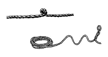
Strand
Distortion - Strand distortion is generally a result of damage caused
by kinking, crushing, bad nips or other violent treatment. Commonly found in berthing hawsers, and ropes
which have to be worked in adverse conditions.
Abrasion - Occurs both internally and externally and is caused by friction over sheaves, leads, sharp or rough objects and grit lodging within strand wires. It is often indicated by
deposits of fine brown powder between strands and flattening
of internal surfaces of individual wire.
Corrosion – is generally caused by lack of lubrication. When wire rope is under tension, the fibre heart and cores are also compressed, releasing oil to overcome friction. The normal methods of protecting SWR against corrosion are galvanising and regular lubrication. During manufacture the rope is impregnated with oil but is generally insufficient to last the rope's life. Additional lubrication should be carried out during service with a light bodied penetrating lubricant.
End
for Ending and Cropping - will both increase rope life due to the wear
points being re-located. If additional
rope can be accommodated on the drum, then this will allow for cropping,
bringing 'new' rope into the system, and will re-locate wear points.
Inspection
of Wire - NSCV compliant wire ropes are certified
to AS 3569 or AMSA recognised ship classification society standards. A
visual and physical examination should take place at regular intervals. Under normal usage, wire rope can be inspected
every 3 months. If a broken wire is
discovered, then it should be inspected more often. A thorough external inspection should include any:
Termination of rope at the drum and other
points
Broken wires, corrosion, deformation, surface
wear, defective coiling
Deterioration due to snatch loading
Lengths that run through blocks,
particularly around sheaves under load
A thorough internal inspection should include opening the lay and:
Check internal lubrication
Degree of corrosion
Indentation caused by pressure of wear
Presence of broken wires
An accurate log should be kept of inspection dates, rope condition, end for ending and replacement. Discard the rope if the total number of broken wires visible in a length of S.W.R. equal to 10 times its diameter should not exceed 5% of the total number of wires constituting the rope (Marine Order part 32). Broken wires are usually the result of fatigue and wear.
Chain
Chain is well suited for use as slings, lashings, preventers as it withstands corrosion and abrasion better than steel wire ropes.
Properties of Chain- Chains are made of mild or special steel, and are of short link, long link and stud link type. Those used for chain blocks are calibrated (i.e. the link sides are made parallel). Chain identification depends on material composition. Welded chains, if tested and marked in compliance with I.S.O. are graded 3 upwards to 9 (higher the number, better the grade).The grade numbers are usually stamped on the chain approximately. Some manufacturers may use letters.
Unmarked chains should be treated as grade 3 (mild steel).

ISO Chain
markings (Grade 3 or L)
NSCV compliant chain
is certified to ISO 1704, AS 2321 or AMSA recognised Ship Classification
Society standards
Anchor cables - Stud link chain has the greater strength and
the studs help to prevent distortion, forming of kinks, and knots thus making
it easier to handle. Short or close link chain is used in small vessels in
preference to rope. Stud link chain is used by larger vessels such as tugs and
landing barges.

A length of cable is known as a shackle or shot, the standard length being 15 fathoms, (90 feet or 30 metres).
The cable is marked from either side of each joining shackle.

The shackles are joined together using a
special joining shackles a shown below. The lugless or kenter shackle has the advantage
that it sits in the gypsy (cable holder) of the windlass just like any
intermediate link of the chain. The tapered pin is rammed home and then capped
in place with the malleable lead pellet.

Care And Maintenance - Faults in chain are not easily seen and should be examined frequently for wastage due to rust, missing studs or distorted links. The following lists bad practice in usage of chain.
Cross, twist, knot or kink a chain
Drag from under a load or use around sharp
corners, without protective padding
Use bolts or bull-dogs clips (compression)
for joining or shortening
Use if over 10% wear or if any elongation in
links
Use any chain for slinging unless it has the
approved SWL tags
Wrought iron chain needs annealing because it is subject to surface becoming brittle, which deepens with time. If not annealed regularly (heated & allowed to cool slowly) it becomes dangerous.
Inspection
of Chain – Schedules are every 6 months for less than 12 mm diameter
and every 12 months for over 12 mm. Chains of mild steel should be
checked for the flexing or bending of links.
Damage to links where a chain has been used around sharp edges, causing
cuts or nicks, is a good reason for condemning. High tensile and alloy
chain have great ability to stretch under shock loads and revert to normal
size. If elongation is apparent while
not under load, it has been seriously overloaded and should be discarded.
Splicing
Splicing can only be learned through practice. To begin, seize the ends of unlaid strands, and seize the rope at the point to which you plan to unlay it.
Eye Splice - An eye splice is formed by unlaying the end of a rope, then turning the end back to from an eye, and tucking the separated strands into the standing part. Natural fibre uses three full tucks and synthetic fibre, a minimum of four full tucks. If splicing round a thimble, tie the rope securely to the thimble with light twine, then splice
Short
Splice -This is used to join two ropes when not required to pass through
a block. Unlay the two ropes and clutch
them together, so that the strands of one rope go alternately between the
strands of the other. Tuck each strand
over one strand and under the next, take two or more tucks with each strand,
then turn the line and do the same with the other rope. Pull each strand up taught. A minimum of
three full tucks for each rope.
Back Splice - Back splice is used in the means of finishing off the end of a fibre rope to prevent fraying. It is commenced with a crown knot, then the strands tucked as in the short splice.

Wire Rope Splicing - There are many types of wire splicing. The other commonest splice used at sea is the eye splice, and though most wire is received on board ready spliced these days, there may be the occasion when a seaman is called upon to do some splicing.
A bench vice is required to hold the wire firmly, a fid to separate the strands, a set of heavy duty pliers and a good deal of muscle. The splicing tail should be about 40 diameters of the wire. Whip the wire at this point, and form the eye and seize to the main part. Unlay strands of each tail down to the seizing and whip each strand with twine, then cut away the heart.
The diagrams give the sequence for the first tuck of an eye splice in common 6 strand rope. After completion of the first tuck, continue tucking each strand over one and under two, against the lay, until 3 full tucks and 2 reduced tucks (with each strand halved) have been completed.
Once the splice has been completed it would traditionally be protected by worming, parcelling and serving. Worming is the process of embedding greased hemp around the gaps between the strands to give the wire a flat surface. Parcelling is bandaging around the wire to trap the greased lubricating hemp, and serving is to overlay the whole with a tight seizing of marlin twine or wire. This would then be painted over with pitch.
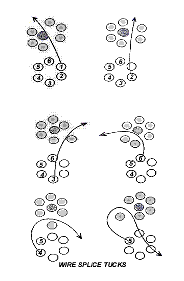
Strength of Rope and Chain
NSCV compliant fibre
ropes are manufactured as per AS 4142.2 and tested as per AS 4143.1 or to AMSA
recognised ship classification society standards.
Stress denotes the load put on material, and strain is the molecular disturbance made evident by a change of shape or a fracture of the material due to the stress which has been applied. The term breaking or ultimate strength is the load or weight applied to material when testing to destruction. Every item used in rigging has a B.S. (Breaking Strength), from which a S.W.L. (Safe Working Load) may be found by dividing the B.S. by a factor of safety for the function of the gear.
Rope (Fibre) - Their relative order of strength is Coir (never to be trusted), Sisal, Manila, Hemp, Polythene, Polypropylene, Terylene and Nylon.
Splicing a rope reduces its strength by at least 10%. Knots reduce a rope's strength by at least 50%. The ultimate strength of fibre ropes depends much upon the quality of fibre and the process of manufacture.
The diameter of fibre and steel wire rope is in mm. A safety factor of fibre and steel wire rope of 1/6 is used in the marine industry. Thus S.W.L. can be taken to be 1/6 of the breaking strength for fibre and wire rope.
An approximate S.W.L. of a Rope = D² x F
kgs.
D is diameter of rope in mm and F is a factor of safety. The S.W.L. is taken to be (1/6 of the breaking strain of the rope)
|
Material |
Factor |
Approximate S.W.L. |
|
Natural Fibre |
1 |
D² |
|
Polyamide (nylon) < 50 mm |
3 |
3D² |
|
Polyamide (nylon) > 50 mm |
2.5 |
2.5D² |
|
Polyester (Terylene) |
2.5 |
2.5D² |
|
Polypropylene |
1.8 |
1.8D² |
|
Polyethylene (Mono) |
1.8 |
1.8D² |
|
Polyethylene (Staple) |
1.2 |
1.2D² |
|
Wire |
8.0 |
8D² |
Example 1 - find SWL of 30 mm Nylon
SWL (kgs) = 3D²
= 3 x 30²
= 2700 kgs
Example 2 - find SWL of 12 mm Wire Rope (6 x 24)
SWL (kgs) = 8D²
= 8 x 12²
= 1152 kgs
It is common practice to allow a 'Factor of Safety' of 6 in general marine work for both fibre and wire rope. Wire slings can have a 'Safety Factor' of 5 in some cases.
Chain - It is common practice to allow a 'Factor of Safety' of 5 for chain. The S.W.L. = B.S. x 1/5 tonnes.
Grade 1 - Mild Steel
Grade 2 - Special Quality Steel
Grade 3 - Extra Special Quality Steel
Stud Link |
Size |
B.S. (Breaking Strength) |
|
Grade 1 |
12.5 mm to 120 mm |
(20D²) over 600 |
|
Grade 2 |
12.5 mm to 120 mm |
(30D²) over 600 |
|
Grade 3 |
12.5 mm to 120 mm |
(43D²) over 600 |
With the I.S.O. standards - Grade 3 is mild steel - Grade 4-9 is tensile steel.
Example - in this case the S.W.L. = 3D² x Grade (kgs)
10 mm Grade 3 chain
SWL (kgs) = 3D² x Grade
= 3 x 10² x 3
= 900 kgs
When calculating SWL of chain, beware of two different identification systems. If in doubt, assume the chain is the lowest grade, (i.e. mild steel).
4.2 Blocks, purchases and tackles
A purchase is any mechanical device which can
increase output power. A tackle is a simple device comprised of rope and
blocks.
Blocks
These are frames of wood or steel fitted with one or more sheaves. They are designated as single, double or treble depending on the number of sheaves, or from some special shape or construction (snatch blocks).
Fibre Rope Blocks - The older wooden blocks had steel sheaves and plain bearing axles. The later type have a steel strap or band running outside the shell, with the sheave pin going through both strap and shell. The modern type tends to be all metal. If no S.W.L. is marked on them, then it is equivalent to that of the largest diameter rope that can be reeved through comfortably. The diameter of sheaves used for fibre rope should be at least six times the diameter of the rope used when hand operated. When power operated the sheaves should be 12 times the rope diameter (diameter in mm).
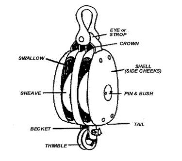
The drawings show parts of a wooden block above and a collection of blocks below. The rope must match the size of the sheave to avoid crushing, kinking and deformation. The diameter of a sheave is measured to the bottom of the groove. For wire ropes the sheave diameter should be 20 times the rope diameter for power operated blocks and it can be 10 times on non power operated blocks.
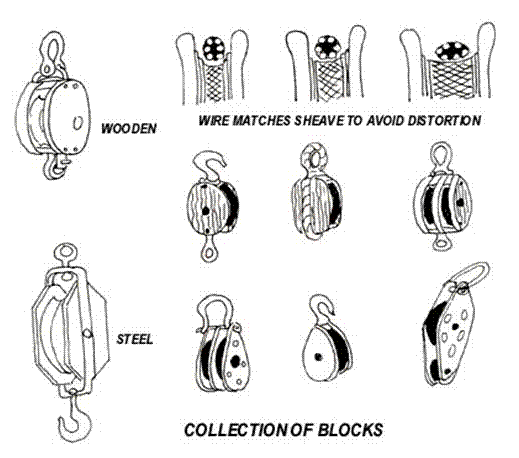
Wire Rope Blocks - Generally referred to as steel blocks and more often used for heavier applications on board a vessel. There should be a small plate affixed to the cheek of the block showing:
Serial
Number
Safe
Working Load
Last
Test Date
Some typical wire rope blocks are shown below.
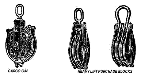
One special type of block that the mariner will come in contact with on occasions is the Snatch Block. This is a small strong steel block with hinged side. This permits the fall to be put over the sheave through an opening in the side, without reeving the end through. They are very handy as lead blocks when moving cargo, or gear around the decks.
Care And Inspection Of Blocks - Check the swivel eyes and sheaves for free movement Grease swivel, shank and bearings regularly.
Examine side plates for distortion.
Check axle pins cannot work loose.
Oil all surfaces rather than paint. (Paint clogs oil holes and hides defects).
Check wooden blocks for splitting.
Never drop a block on the deck.
Purchases and tackles
The lifting power of a purchase or tackle is referred to as the Mechanical Advantage ratio (MA). MA depends on the number of sheaves in the block and how much rope is moved by rigging it to advantage or to disadvantage.
To find the MA of any purchase, count the number of parts of rope at the moving block. (This assumes no friction in the sheaves and no benefit of counterbalancing the hauling persons own body weight). In the Gun tackle below the ratio is 2:1.
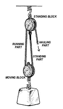
When hauling from the moving block, the
tackle is rove to advantage. In comparison, rove to disadvantage is when
hauling, from the standing block. A Gun tackle
is shown below rigged to advantage and disadvantage.
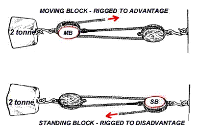
Where the tackle is rigged to disadvantage
the mechanical advantage is the same as the number of sheaves in the tackle (MA
2:1- stress to lift 2 ÷ 2 =
1 tonnes) and when rigged to advantage it becomes the number of sheaves plus
one (MA 3:1- stress to lift 2 ÷ 3 =
0.66 tonnes). This is because the gear like action of the greater length of
rope needed to haul through the tackle in advantage
to move the weight the same distance.
The tackle above is called a gun tackle.
Ingenious use was made of the twin ratios in the operation of historic warships
cannons’ to quickly run the guns out for firing and enable greater friction to
control the recoil after firing.
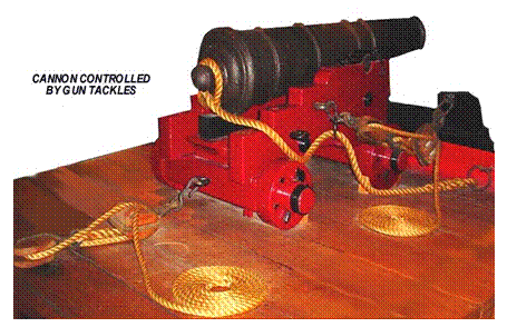
Types of Tackle - Special names are given to the various types
of tackle used at sea, many of which owe their origin to their former use in
the sailing ships of the last century.
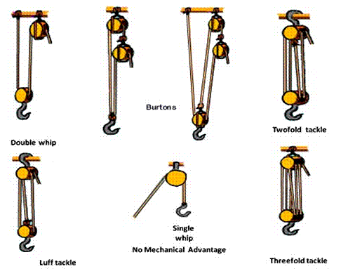
Chain Hoists (Chain Blocks) - Chain blocks are used for lifting machinery found in the engine room. Due to the slow movement of the load, it can be placed with precision. They should be constructed with the lower hook as the weakest part, so it will start to spread before the hoist is overloaded. Evidence of spreading or wear is cause for replacement. Any distortion of the chain links means it has been overloaded and is unsafe to use.
4.3 Access- stages,
bosun's chair and rope ladders.
Rigging a Stage
A practical size line for a stage rope is 20
mm. Lay a scaffold plank suitable to
take the weight to walk on over a square horn timber and bolt them together.
Lash together as shown below by taking turns of the hauling part around the end
of the stage and the horn as a means of lowering. The rope tail is made fast to
the standing part after the hitch is completed, using a bowline. The standing
part should be reeved through a lizard, shackle or best of all a block to
enable it to be lowered and adjusted by those working from the stage. The fall
beyond the bowline must be long enough to reach the waterline (a gant line) for working over the ship's
side.
If the stage is extra long, it is advisable
to rig a centre line to prevent sagging in the middle.
Precautions
- Inspect stage, lines and
fittings for correct rig and free of defects.
Load
test the stage to 4 times the intended load.
Always
set down before raising and lowering.
Gantlines
must trail in the water to be used as lifelines.
Stages should only be rigged over water, not used whilst underway and be positively attended with a life buoy ready and available to deploy. Rig a rope ladder for access.

Rigging a Bosun's Chair
A bosun's chair and gantline is used in work
done aloft. The traditional rope bosun’s chair has been superseded by modern propriety
safety harnesses. Not only are web harnesses much more comfortable than rope,
but they are accurately rated for the loads of personnel and tools that will be
carried aloft.
Additionally modern climbing accessories and
fittings such as ascenders, descenders, carabineers with stretchable ropes
provide far greater levels of protection than the traditional rope supported
chair (stretch factored climbing ropes reduce the snatch force experienced as a
rope takes up the weight of a person’s fall). The rope chair is therefore
described here for historical interest only.
In the traditional chair the gantline is
attached by means of a double sheet bend and end seized to the standing
part. The gantline should be reeved
through a tail block or lizard for ease of hauling and lowering oneself.
Precautions
- Correctly rig the gantline and
inspect all lines, fittings and chair for defects.
Load
test 4-5 times the intended load.
When
hauling aloft in a bosun’s chair it should be done by hand.
Ensure
that no tools can be dropped (use lanyards) for the safety of personnel below.
If
riding a stay ensure the bow of the shackle rides the stay and mouse the
shackle pin.
Wear
a safety harness if more than 2 metres aloft.

The
practice of holding on with one hand and making the lowering hitch with the
other hand is dangerous. Without weight
on the chair, seize the fall and gantline together above the thimble eye of the
support ropes (or use a propriety abseiling
descender) before making the lowering hitch. A long bight of the hauling
part is pulled through the strop of the chair, passed over the head and
allowed to drop behind to the feet. It
is then passed under the feet and brought to the front. The slack on the hauling part is pulled tight
forming the hitch. When ready to lower, feed
slack on the hauling part through the hitch or abseiling descender as utilised.
Portable
Ladders
Rope ladders are light and suitable for low
height only. The top of the ladder can be left with the rope ends whipped or a
thimble can be used.
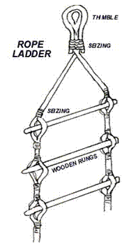
4.4 Lifting gear
Shackles, hooks and strops.
Specification for lifting gear is found in Marine Orders 32 Cargo Gear.
Shackles are used as connectors of one wire to another, a sling to a load, a hook to a block or a hook to a wire rope eye. Their nominal size is given by the diameter of the shackle body.
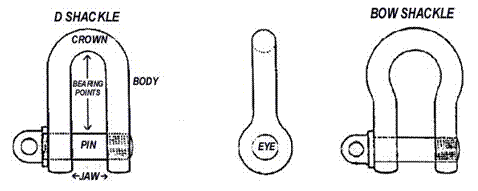
The two principal designs are D and Bow shackles, shown with screw pins above. Bow shackles are used when more than one attachment is to be made to the body.
Other types of shackles are usually named in relation to the pin type, including the forelock shackle that is used for standing rigging, or where vibration is present. The pin is unthreaded, but it has a flat split pin as a keeper.
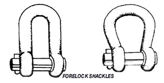
Safety
checks with shackles - Any
shackles used in lifting purchases must be tested and have the SWL marked on
the body. Never use a pin that is bent, strained or damaged in any way. It is
poor practice to replace a shackle pin with a nut and bolt that may bend under
load. If the crown or pin is worn to more than 10% of its original diameter it
must be discarded.
All permanently attached shackles should be
the locking type or should be moused (secured
against accidental opening by wire seizing).
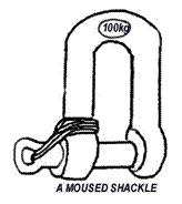
Avoid using a common shackle where the pin
can roll and unscrew under load (i.e. as a slide along a wire stay or with
strops).
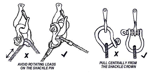
Do not allow shackles to be pulled at an
angle. Pack the pin to hold it square on
the hook.
Hooks - Hooks are used to attach the load.
Because of its open construction, the hook is usually the weakest part
of the lifting rig. New hooks are
stamped with their S.W.L.
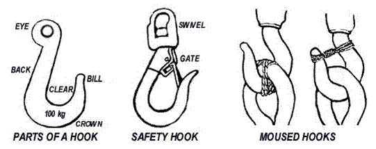
Safety
checks with hooks - When used
for raising or lowering cargo they should have a device to stop the slings
jumping off. Hooks should be free to rotate under all conditions of loading. Swivels
should be inserted wherever a twist is possible. If the hook throat opening has
stretched more than 5% it must not be used. Damaged, distorted or bent hooks
must not be used. The throat opening must be large enough to fit the largest
rope, ring or shackle to go on it. Do not overcrowd the hook. Use a bow shackle or ring.
Slings
and Strops - are made from
fibre rope, wire rope or chain.
Fibre Rope lifts without scratching, protect load surfaces
and are flexible.
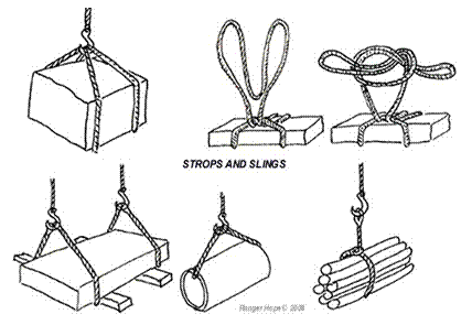
Steel
wire rope slings are more
suitable for lifting machinery or material that will cut easily into fibre
ropes. Size for size they are much
stronger than fibre rope slings but are more expensive. New slings will have
their Working Load Limit stamped on them.
Chain
Slings are stronger than
both wire and fibre rope and are often used in combination with them,
especially the two, three and four legged variety, when lifting bulky loads and
machinery. The collar sling can have
different sized end links so that one may be rove through the other to act as a
choke hitch. New chains will have
their Working Load Limit stamped on them.
To shorten a chain sling if no clutches
available, pull slack of chain through the large ring to form a bight. Pass one hand through the bight, catch hold
of standing part, let everything else drop and place standing part over the
cargo hook ready for heaving.
Working Load Limits - New chains will have their stamped on them.
It must be appreciated that the stress on the
spread arms of a sling will increase with the angle that they make at the
swivel hook. Therefore the shorter the strop (from load to hook) the less load
can be safely lifted to remain within the Working Load Limits.
Derricks
Even though the traditional derrick is now seldom
seen handling cargo on smaller trading vessels, the principles of its use apply
to fishing and sail equipment. A boom
or jib is attached to the mast at a gooseneck (hinged fitting). The jib can be raised or lowered by use
of a topping lift cable, in order to
position the cargo swivel hook
vertically over the cargo hatch or over the shore side wharf for unloading.
Both union purchase rig and a mast with single boom used as a derrick to unload
a cargo are shown below. Safety cargo netting is omitted for clarity.
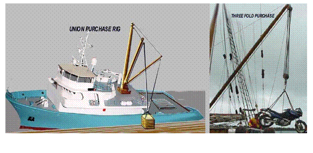
The boom is held steady (stayed) by guy tackles
and their pendants are made fast. A
winch (capstan) can then control the cargo
runner with its attached swivel hook and load. The disadvantage of this
system is that repeatedly swinging the boom from over hatch to over the shore
requires temporarily securing a preventer line and re-adjusting the guys for
each lift and lowering - a time consuming task. This problem is resolved by the
union purchase rig that uses twin
booms, one stayed above the hatch and the other above the wharf. The cargo
runner from each boom is attached to a single swivel hook so the load can be
swung from one boom over to the other. Care must be taken not to pull up the
load so high that the two cargo runners are pulling against each other, with
the consequence of severe overload (the angle between the load and the two
cargo runners must not be greater than 120º).
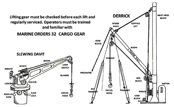
The safe working load is painted on the derrick boom or jib
The union purchase rig is replaced in modern
cargo vessels by tandem or dedicated cranes for heavier lifts. For smaller
lifts, retractable jib hydraulic cranes of the slewing davit type, (HIAB or
Palfinger) are now widely used as general purpose cranes to address the
disadvantage of derrick system’s slewing (swinging) limitations
The slewing davit above may be slewed in either direction through 360º, often by means of a manually driven gearbox. To prevent movement when not in use it is fitted with a locking device. Hoisting is achieved by operation of an electric/hydraulic motor mounted on the davit. Raising and lowering is affected by a remote control with separate buttons for up, down and emergency stop. The winch is equipped with a centrifugal brake, and a limit switch cuts the motor if the swivel hook is drawn too close to the jib head.
Lifeboat
davits
The considerable amount of running rigging
(rope or wire) and exposed position of traditional davit lifeboat launching
systems make them prone to jamming due to deterioration or corrosion. They must
be regularly maintained and operationally tested for the trying conditions that
will prevail when needed for use in earnest.
An emergency signal will call crew to their lifeboat
muster station, named by the letter P or S (port or starboard) and boat number
(numbered from bow to stern). On instruction of the leading hand life jackets
are donned, the lifeboat (with equipment and supplies) is readied and secured
with temporary bowsing lines.
Radial davits - are normally operated with rope tackles or manual winches. After the abandon ship signal, if all is clear below, the securing gripes are let go and the lifeboat hoisted on both radial davits to clear the chocks. A guy or bowsing line from the after davit is hauled taught, pulling the lifeboat backwards sufficient that the forward davit can be rotated outboard and the bow of the lifeboat swung out. Next the guy or bowsing line from the forward davit is hauled tight pulling the lifeboat forwards sufficient that the aft davit can be rotated outboard and the stern of the lifeboat swung out ready to lower. If safer to do so, passengers may be boarded at that stage and controlled lowering can commence.
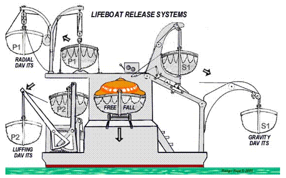
Luffing davits - are wound out (manually or more commonly with
electrically driven screw). To enable sufficient outboard clearance for the
lifeboat on its descent they require a greater height of davit to meet Class
rules requiring life boats to be successfully lowered from the high side with
angles of heel up to 15º. Consequently they are more often sited at the
extreme ends of a vessel.
Gravity davits - enable larger outboard clearance for the
lifeboat with compact stowage. A release
is initiated by freeing the brake. The weight of the vessel is used to slide
the lifeboat down the skids. From this position continued release will allow it
to be deployed.
A safe boarding station is provided on the
deck below the skids. This system is suitable for larger capacity lifeboats but
being more complex than those before it requires a fastidious attention to
maintenance and greasing to ensure free running.
The problems of deterioration or corrosion
inherent in davit launching systems are being avoided in non passenger vessels
by the use of free fall lifeboats. As with canister liferafts the release
mechanism and the skids need comparatively minimal attention, however the
importance of personnel restraints functionality and structural/watertight
integrity of the lifeboat (that may free fall may metres) cannot be
overstated.
Safe use and maintenance of lifting
gear.
There is always a danger whenever weights are
to be lifted or moved by means of cranes, booms, tackles, topping lifts or
other appliances due to the unevenness of the working platform and changes in
dynamic loadings on the gear. Therefore
the correct and safe use of the gear, machinery and associated hardware is of
vital importance, as is its care and maintenance.
Preparations
for moving lifts - Inspect all
equipment for defects. Determine weight of load and position of the centre of
gravity in relation to the lifting points. The safe working load of the
equipment must never be exceeded. A lifting appliance is only as safe as its
weakest part. Decide upon the method of slinging and lifting the load. Take
into account whether the lift requires tag lines (to steady the load from
swinging wildly or position it in tight spots) and packing or chafing pieces.
Ensure the load is free to be lifted (not still
bolted down or lashed) and any loose parts secured or removed.
Make sure there is a clear method of
communication between the operator and the signal man and that the plan is
understood by all. Be aware of the code of hand and whistle signals if operating
with a crane or derrick. Some commonly
used hand signals are shown below. Only one person should signal a driver at a time; however the driver
should obey anyone who gives the stop
signal to indicate an emergency. High visibility gloves or armbands may be
worn by the signaller to show his/her authority and to make the signals clear.

The operator must not pass a loaded boom over
personnel, so stay out from under or between loads and any solid obstruction
against which you could be crushed. Never keep a load in the air any longer
than necessary. Heavy weights should never be allowed to drop no matter what
the distance.
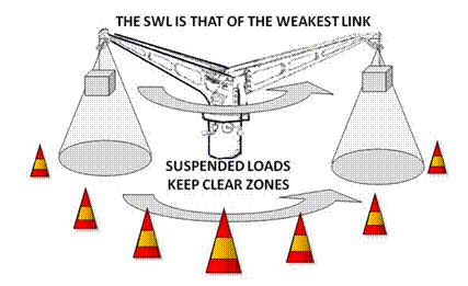
The
lift - The greatest force must
be applied at the time of starting a load, in order to overcome inertia. Apply the load gradually to avoid exceeding
the SWL. Check the load's balance and
general security. If this is satisfactory speed may be increased once the load
is moving dependant on safety and smoothness of operation. All motion with
heavy weights should be slow to avoid creating momentum.
Avoid swinging the load. If you're lifting something off a wharf, drag
it until the load is directly under the head of the crane or boom. Remember
those tag lines to steady to heavy unwieldy loads. When lowering, stop a short
distance above the landing site to allow steadying, to check position for
landing, dunnage, and to make sure the slings will not be caught under the
load.
Avoid sudden shocks or strains and side pulls
as this puts great stress on lifting gear.
Listen for changes of sound in a wire, rope
or block. Wire or cordage normally hums under strain. If it starts to squeak or squeal, watch
out. A faulty block may give warning by
squeaking or groaning. Never use running gear as a handhold.
Check lifting equipment before returning to
stowage.
4.5
Deck machinery
Warping, capstan, winch and windlass
Warping winches/windlasses and capstan
winches/windlasses differ in that the drum of the warping winch is horizontal the
capstan is vertical. Warping winches tend to be favoured for use on merchant
vessels whereas the capstan is more common on naval vessels. The requirements
for safe operation of both types are similar. (Warping is the act of hauling or moving a vessel fore or aft
usually along a wharf, or when adjusting mooring wires/ropes.) In merchant
vessels, a warping drum is usually included as an extension at one or both ends
of a windlass or winch, so that that the motor can be utilised for more than
one function.
A line may be surged out (let go without restraint), veered out (let go under control of a brake) or walked out (by mechanical rotation under
power). Never surge a synthetic line on a rotating drum. Surging causes
friction, heat is generated and synthetic fibres may melt onto the drum and
part.
Survey requirements for deck machinery -
Windlass/capstans, winches and other machinery must be operated in accordance
with Safety Management operational procedures that address Marine Orders 32 Cargo Gear and the NSCV Part C Section 7 Subsection 7D-Anchoring and Mooring
Equipment.
Older vessels may comply with USL Code
Section 9 Engineering. These regulations require a
windlass to be:
Provided
with cable stoppers (or devils claws) between the windlass and the hawse pipe
Designed
for immediate dropping of the anchor
Provided
with an efficient brake
For an anchor of less than 50 kg, a windlass
may be hand operated. This is provided that the applied effort shall not exceed
155
It should be noted that lifeboat davits and
other mechanical launching arrangements are also deck machinery. The
requirements can be found in NSCV Part C
Subsection 7A-Safety Equipment. Older vessels may comply with USL Code Section 10 Lifesaving Appliances.
Wear good safety footwear wear, gloves, clothing that is not loose and avoid standing in the direct line of the hauling part or in the bight of lines. Keep the area clear of passengers and unnecessary crew and take extra precaution in wet weather. You should never manually guide the wire rope onto an operating winch drum (barring over). This is a very dangerous practice.
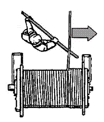
The
thumb rule as drawn below is used to determine how to start winding the wire or
rope onto a winch drum. With the pad of the index finger touching the over wound
or under wound wire, the thumb will point to the correct side of the drum.
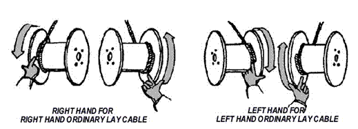
If you need to assist wire rope onto a drum (when loading a new rope) always use a guide tool, never use your hands.
Winch Operations
Prior to operation always inspect that the winch is clear (not fouled), the wire rope is roved correctly, all fittings are serviceable and the controls are unobstructed. Inform crew and keep personnel clear before test operating the winch to check that the:
Controls and interlocks are operating
correctly
Brake and pawl functions are working
Wire rope is correctly spooling onto the
drum
Never use the winch end terminal as a stop. Leave at least 2 turns on the drum when fully unwound. Continually check the system whilst operating.
Where the winches run on electrically-operated hydraulic pumps, they can be run out under power. This gives the operator much greater control and eliminates the ever-present risk of brake failure which can result in lost or damaged gear.
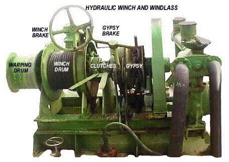
In most cases careful manipulation of the hydraulic control allows them to be slowed right down to a bare crawl and, in the neutral position, acts as a brake when the hydraulic motor is running. All such winches have a manual brake as standard.
Safety - The operator is directly responsible for the safety of gear handling operations. If there is any doubt about safety, stop the machinery immediately and rectify the problem or isolate the system. The operator must know the SWL of the equipment and operate within the designed limits of the winch.
Operators should never leave machinery unattended with gear running, or with a load suspended. Avoid overwinds of cable. Always be sure everyone is clear of the danger zone before applying a load, and never pass a suspended load over another crewman. Machinery should be provided with a means to prevent over-hoisting and to prevent the accidental release of a load if the power supply fails. Check you know where the Emergency Stop button is for all machinery.
Machinery guards should always be in place, except when carrying out repairs. Never work on running equipment, it must be stopped and rendered incapable of accidental restarting. Be sure the area around the controls is unimpeded, and that your view is as unobstructed as possible. Make sure that all lighting is in working order and that guards protect the globes.
Warping Drum Operation - Always test a winch prior to use for warping. (Warping is to haul a vessel along a wharf when adjusting lines.) Normally pass 2 - 3 turns around
the drum and tail the line (keep
strain on the rope as it passes over the warping drum) keeping about a metre
away from the drum surface. If it slips on the drum add more turns.
In merchant vessels, a warping drum is
usually included as an extension at one or both ends of a windlass or winch, so
that that the motor can be utilised for more than one function. In such cases
it is necessary for both the main winch drum and the warping drum to be capable
of being clutched or de-clutched from the mainshaft. This is so that both can
operate independently. If this is not the case, when using the warping drum, any wire coiled on the winch drum (runner) must be removed before using the
winch for warping.
In the case of windlasses being operated for
the purpose of warping, the cable lifter (gypsy) should
be disconnected (de-clutched) from
the mainshaft.
Warping a vessel is a skilled operation and requires
one end of a wire or hawser being fastened on a bollard on the wharf. The wire
then goes through a fairlead or guide on the vessel to the warping drum on the
winch.
The wire is loosely wrapped around the drum
and the remaining loose end coiled nearby. The winch is set in motion, but as
the wire is loosely wrapped it slips and does not move with the rotation of the
drum. On the signal to haul the operator pulls on the loose end of the wire,
this tightens the wire on the drum. Due to the friction between the wire and
drum, the wire is hauled in around the drum and at the operator’s end is pulled
off the drum and the vessel slowly moves.
The skill in warping comes from the
operator’s ability to adjust the pull on the wire so that the hauling is
smooth. He can adjust the speed of hauling, up or down, by increasing or
reducing the pull or allowing the wire to slip at a controlled rate on the
drum. The balance between hauling and slipping is critical and it may be
necessary to quickly wrap extra turns around the drum or reduce the number of
turns without getting entangled in the wire.
Passing
a Stopper - If a riding turn develops (where the line
overruns itself leading to jamming), stop and remove with caution (riding turns
usually develop because of incorrect lead or tailing). If there is strain on the
line then use a stopper to
temporarily take the strain.
A stopper is used to transfer the weight on a
line from one fitting to another, such as a warping drum to a bollard.

It is secured to a strong point and led along
the tight line towards the strain. The tail is half hitched around the line
against the lay and passed around with the lay. The end can be held or whipped.
When attached, the tight line can be eased off the warping drum allowing the
load to be transferred onto the stopper. Use a natural fibre stopper on a
natural fibre line and synthetic for synthetic line - do not use a nylon cord for
stoppers.
Anchor windlass operations
A
windlass consists of a chain gipsy (or gipsies if more than one anchor is
involved) and may have one or two warping drums at either end. To enable these
components to be operated separately, dog clutches and brake bands are fitted.
Before starting the motor- check
that the area is clear of ropes/wires and other gear. It may be necessary to
start the motor to take the load off to remove stoppers, claws or lashings, a
process called clearing away. While
clearing away ensure all clutches and brakes are in the appropriate position to
avoid an unintended let go of the anchor.
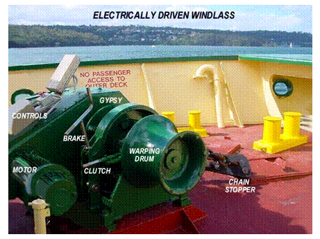
At all times, stand aft of windlass and ensure you are not in line with the run of the cable. Keep clear of warping drums (if they cannot be de-clutched)
.
|
The
steps to lowering the anchor with a windlass – letting go the anchor |
|
|
|
|
| Step
1: Brief the crew |
|
| a. |
Clear communication between the Master/supervising officer and the crew
are required in anchoring procedures. While the use of hand held radio
is used in vessels so equipped, non verbal hand signals for commands
and acknowledgements must be agreed for alternative use/backup. Hand
signals are not effective if eye contact between parties is not maintained. |
| Step
2: Clear away |
|
| a. |
Check the windlass pump’s hydraulic oil level in the supply tank, start
the pump, check for leaks. |
| b. |
Engage the dog clutch for the chain gipsy (may require the dog clutch
lever to be rocked between raise and lower positions to engage/disengage).
|
| c. |
Slowly release the gypsy’s brake and wind in the chain cable to take
the weight off the devil’s claw or stopper. |
| d. |
Re-apply the brake and ensure it is holding. Clear away (remove) the
devil’s claw or stoppers. |
| Step
3: Let go |
|
| a. |
Ensure there is nothing in the way of the anchor being dropped, the vessel
is stopped or moving astern, and all personnel are clear of the cable
or bights in any attached buoyed lines.
|
| b. |
Dependant on the water depth and /or urgency, the master will determine
if the anchor is to be: i. walked out (let go under
power) ii. veered out (let go under
partial braking the gypsy) iii. surged out (let go freewheeling
the gypsy) Eye protection must be worn as metal scale & rust from the chain
will be shed as it passes through the gipsy. |
| i. |
Walking out. Ensure the dog clutch is engaged, release the gypsy brake,
and operate the windlass pump control to let out the cable. |
| ii. |
Veering out. Ensure the dog clutch is disengaged; release the brake slowly
allowing the anchor cable gipsy to partially freewheel under control
of the brake. |
| ii. |
Surging out. Ensure the dog clutch is disengaged; release the brake allowing
the anchor cable gipsy to freewheel. Stand clear. This method is not
advised in deep water. |
| Step
4: Make fast |
|
| a. |
When the Master considers sufficient chain has been let out, put the
brake on tight, ensure the dog clutch is engaged. |
| b. |
Check that the vessel is not dragging its anchor, (by monitoring its
relative position with transits). Display anchor day shapes or lights |
| c. |
If anchoring for an extended period, re-apply the devils claw or stoppers
and switch off the oil supply pump. Maintain an anchor watch. |
When lowering cable check that dog clutch is clear of cable lifter. Release brake sufficient to control the run out speed of the cable. If lowered too quickly it may whip and jump on and off the cable lifter.
|
The steps to retrieving an anchor – to
weigh anchor |
|
|
The Master must steam the
vessel towards the anchor cable, taking the weight off to facilitate
retrieval. From his/her position, the cable cannot be seen. The direction and
the elevation of the cable must be communicated continuously by the foredeck
crew to the master. |
|
|
Step 1: Brief the crew |
|
|
a. |
As the cable is leading
seaward, the direction and elevation hand signals given by crew persons are
easily masked (from the master’s viewpoint) behind their bodies. They are not
effective if they do not maintain eye contact with the supervising officer. |
|
Step
2: Clear away |
|
|
a. |
Check the windlass pump’s hydraulic oil level in the supply tank,
start the pump, check for leaks. |
|
b. |
Engage the dog clutch for
the chain gipsy (may require the dog clutch lever to be rocked between raise
and lower positions to engage/disengage). |
|
c. |
Release the gypsy’s brake
and wind in the cable to take the weight off the devil’s claw or stopper as
may have been fitted. |
|
Step Step
3: Weigh anchor |
|
|
a. |
Continue winding in the cable, as the crew signal the direction and
elevation of the cable to the supervising officer. |
|
b. |
The crew should additionally signal when the cable is standing
vertically. The crew should additionally signal if the vessel runs over the cable. The crew should additionally signal when the anchor breaks water, the
windlass should then be slowed. |
|
Step Step 4: Clew up |
|
|
a. |
Before the anchor is
fully drawn up into the hawse pipe it may be convenient to hose off the
attached mud while it is still over the side. |
|
b. |
In pulling tight into the
hawse, the windlass should be slowed right down to ensure the flukes are
positioned correctly. |
|
c. |
Once the anchor is
housed, put the brake on, attach the devil’s claw or stopper, disengage the
dog clutch and turn off the pump. |
Caution - The
windlass is in an exposed position on the foredeck or forecastle.
The deck area is often wet and could be
slippery. Wires, ropes and cable and fittings are hard to handle. Non-slip
footwear and heavy duty gloves should be worn.
When riding at anchor - fit the chain stopper, claws or lashings to secure the cable.
Release the clutch so that the anchor and cable weight is carried on its stopper and the windlass is isolated from load and shocks.
When
the anchor is fouled - If
the anchor does not break ground while being hauled vertically, then it may be
fouled. Engage the brake on the winch and slowly drive the vessel forward to
see if this clears the anchor. If this doesn’t work, try making the anchor
chain fast with cable stoppers and the run the vessel slowly in wide circles on
a taut line.
It
is essential to secure the chain by the cable stoppers to avoid strain on the
windlass.
When it is impossible to break free, the
vessel should be run up as close as possible, a float marker that will be
visible at high tide attached to the chain on the anchor, and the
chain broken at the nearest shackle. The scope of the marker must be of
sufficient length to reach the bottom at high tide. This will enable retrieving
the anchor later. Sudden jerks or extreme
tension can bend the shaft on which the gipsy is fitted.
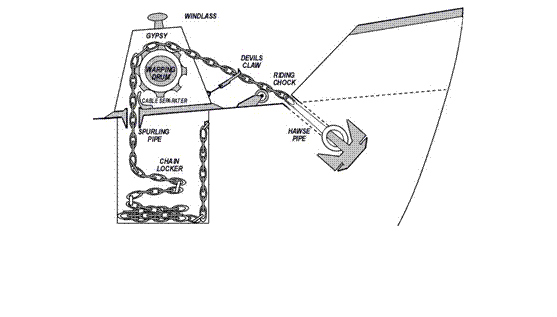
Mechanical
faults in deck machinery
Deck machinery is built to basic robust designs
that have withstood the test of time, but it is exposed to weather, can be
mishandled, overloaded or suffer from poor
maintenance.
Windlass- common
problems for include bent shafts due to overloading arising from allowing the
load to be carried by the windlass when the anchor is fouled in the ground,
instead of breaking it clear by putting the load on the chain stopper and
pulling the anchor hard home such that the windlass is overloaded.
Lack of maintenance resulting in wear in
bearings and shaft in way of bearings, worn linkages causing slackness (thus
making operation of the gear difficult), lack of brake maintenance (resulting
in reduction in braking effect or break failure).
Winches - Bent
shafts due to overloading arising from exceeding the safe working load,
allowing the cargo hook to jam in the derrick head or lack of maintenance
4.6 Hydraulic
power units used in winch application
The main components required to drive a hydraulic powered winch are a:
Hydraulic pump to convert energy from a
motor into hydraulic energy
Hydraulic motor to provide the hydraulic
power at/to the winch
Discharge and return piping between pump and
motor
Directional control valve for winch motor
control and operation
Over pressure controls at strategic points
in the system
Filter (usually in the hydraulic oil return
line)
Oil tank (sufficient capacity for return oil
to settle and cool, before re-cycling)
Heat exchanger (if necessary) to cool the
hydraulic oil
Where other deck equipment (windlass, cranes, capstans etc) is hydraulically operated, the discharge and return piping can be laid out as a ring main with tappings to each hydraulic motor. Then only one hydraulic pump is required to serve all the equipment.
It is common to locate the pump in the main machinery space. In some vessels, other locations may be considered more suitable. The size of a pump is determined by the anticipated peak load, based on the cycle of operation of the equipment.
Hydraulic pumps- are described in Chapter 2.4, but can include the following range:
Simple external or internal gear pumps
Screw, vane and cam pumps
Axial
piston operated by swashplate or tilting head in line piston and radial piston
pumps
The former are fixed displacement pumps and
the latter variable displacement pumps. Internal relief systems from discharge
to suction are provided to prevent over pressure.
For deck machinery hydraulic pumps must have
pressure relief protection on the discharge side which shall operate in a
closed circuit. Materials of hydraulic pumps, motors and accessories must be
compatible with the working fluid. Hydraulic fluid must be non-flammable or
shall have a flashpoint of 1570C or over. Hydraulic hose must comply
with AS. B-226. Installation and fittings must in be
accordance with the manufacturer’s requirements.
Hydraulic motors - Most
designs of pumps are capable of operation as motors. If this is the case, oil
under pressure from the pump is admitted via the directional control valve to
the forward or reverse port of the motor. This will turn and rotate the output
shaft in the desired direction.
The load requirements for a winch are a high
starting torque, which are not provided in some of the designs mentioned. This
has led to the development of slow speed, high torque motors of the radial
piston type which are suited to cargo winch operation.
Hydraulic motors are protected against
overload by relief valves. On loss of hydraulic power (usually failure of
electrical power source) a brake is spring loaded to the stop position. It is
moved to operating position by a hydraulic cylinder whenever the control lever
starts the motor. If there is a failure of hydraulic pressure or electric
motor, the brake returns to the on position and stops the winch.
Survey requirements for
hydraulic equipment
Initial Survey - At
the initial survey during construction, survey of all hydraulic equipment is
required. As the equipment is new, this would normally be confined to
operational tests to ensure the equipment performs satisfactorily.
Annual survey - An
inspection of all pipe arrangements. In this case, if the hydraulic power
source is located in the machinery space, and the motor for equipment such as
winches is on deck, the piping between pump and motor is to be inspected.
General inspection of machinery installation
(this will include hydraulic pumps) and electrical installation.
Hydraulic winch and windlass maintenance - Routine
maintenance is required to ensure better and more efficient operation of that
machinery.
Inject
grease into all grease points including the main bearings.
Oil
all linkages. Use penetrating oil if needed
Oil
or grease the threads on spindles of brake operating gear.
Check
motors in accordance with the manufacturers instructions.
Ramps
There are many and varied types of ramps.
When in use, if the hydraulic system fails, the ramp should remain in place. Where
ramps are held in position by hydraulic rams, check all valves in the supply
line. This will prevent the ramp falling under its own weight. As an added
precaution, fit mechanical locking devices.
Chapter 5 Steering Gear
5.1 Survey requirements for steering systems
Performance
The
NSCV Part C, Section 5, Subsection 5A.6 - Machinery (USL
Section 9) specifies requirements for steering
systems for vessels of less than 35 m in measured length. The steering gear must
be designed to withstand maximum helm at maximum ahead and astern speed. The
steering arrangement must be such that the person at the helm has a clear view
ahead while at the normal steering position.
Rudder movement must
be no less than 35° to port to 35° to starboard. In vessels of 12.5 metres the
steering gear must be capable of putting the rudder over from 35° on one side
to 30° on the other in 30 seconds when the vessel is at maximum ahead service
speed with the rudder totally submerged. It must not allow prevent violent
recoil at the wheel.
All vessels, except twin screw vessels, must be fitted with
two independent means of steering unless steering is normally achieved via a
hand tiller. The secondary or emergency means of steering shall be capable of
being brought speedily into action.
A rudder position
indicator in full view of the person at the helm must be fitted on all vessels
of 15 metres and over (not applicable at the emergency steering position).
Construction specifications are detailed in the drawings below courtesy of NSCV Part C, Section 5, and Subsection 5A.6.
5.2 Rudders
Conventional (passive) rudders
Passive
rudders use a streamlined hydrofoil blade that can be turned around a vertical
axis and (depending on the relative position of the blade’s centroid) are defined as:
Unbalanced rudder - where all the rudder area is aft of the
turning axis
Semi-balanced rudder - where some of the rudder area is forward of
the turning axis
Balanced rudder - where more than 25% of the rudder area is
forward of the rudder axis
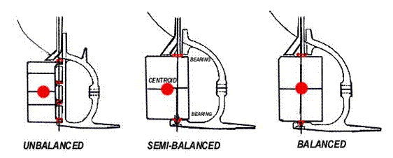
The centroid of the rudder blade area is the
position of the centre of effort acting upon the blade when turned against the
water flow. The turning effort (needed to move the helm) required for
semi-balanced and balanced rudders is less than that for unbalanced rudders. The
part of the rudder forward of the turning axis provides a turning moment
assisting rudder movement once the rudder is moved either side of amidships.
Because of the reduced turning moment (torque) a reduction in rudder stock diameter
is permissible.
Two common types of rudder are shown below. The heel supported or pintle type arrangement is very securely mounted by bearings at the deck, under the hull and under the rudder at the heel or sole (an extension to the keel).
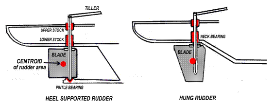
The rudders are secured to the stock by flanged couplings. These also need to be carefully checked whenever the vessel is out of the water.
The hung rudder shows a mounting arrangement where the forces on, and the weight of the rudder are carried by the rudder stock. This means that the stock and bearings need to be of greater size and strength to withstand stresses concentrated around the neck bearing form forces acting upon the centroid. Visual inspection of the rudder stock under these bearings is very limited without withdrawal and dismantling.
Rudder attachment
The attachment and support of rudders depends on rudder type of and the design of the stern area. Larger vessels will usually be constructed with supported rudders, while yachts and small commercial vessels may have hung or spade rudders.
Vessels
with a sternpost require an
unbalanced rudder. Therefore the connection of the rudder to the frame is by
gudgeons (eyelets) on the forward end of the rudder, and matching gudgeons on
the aft end of the sternpost. Pintles (pins) are fitted through rudder and post
gudgeons and form the axis around which the rudder turns.
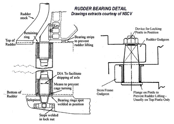
The
stern framing of semi-balanced or balanced rudders has no sternpost. The rudder
is connected to the sternframe at the top and at the bottom by means of an axle
passing through the rudder itself.
The
axle is flanged at the top and bolted to the sternframe. It is tapered at the
bottom to fit a matching hole in the bottom (solepiece) of the sternframe.
Upper and lower bearings are fitted in the rudder. Part of the weight may be
carried by thrust faces on the bottom of the rudder and top of the solepiece.
The
weight of some balanced or semi-balanced rudders is carried totally or in part
by the stock and a rudder carrier (also known as a Pallister Bearing). This comprises a base frame with thrust face
fixed in the steering space. Keyed and fixed on the rudder stock is a collar
which is the upper thrust face. It transfers the rudder weight to the thrust
face of the base frame. The upper and lower thrust faces are either flat or
conical and are grease lubricated.
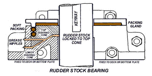
Note:
A gland or seal is fitted where the stock enters the hull to prevent water
entering.
This
gland may be combined with the rudder carrier.
Except
for some smaller vessels the rudder stock is always separate from the rudder.
This is to facilitate removal of the rudder without disturbing the tiller and
steering gear. The rudder and stock are joined by means of flanges on the
bottom of the stock and top of the rudder secured by bolts. Usually the joining
flanges are horizontal but vertical faced flanges are occasionally used.
Checking rudder stock and pintle bearing
wear
The rudder is used to guide the vessel’s direction. This is particularly important if the vessel has only one engine and the balancing of power from a second engine cannot be used to assist steering. It is important to include the rudder system in routine maintenance to ensure it remains in satisfactory working condition. In most cases, if a rudder fails it will occur under load at the most difficult time. This may disable the vessel’s steering and result in a loss of control.
If the rudder has been poorly constructed or allowed to deteriorate, the rudder stock could break loose within the rudder itself. This will result in the rudder stock effectively rotating inside the rudder while the rudder remains still. If there is any sign of separate movement between the rudder stock and the rudder, the rudder should be replaced.
The wear of pintles or bearings can be checked by feeler gauges. Clearance must be taken fore, aft, port and starboard as the pintles and stock are vertical and may not be lying central in the bearings. Jacking the rudder hard one way (as for shafts) is an alternative, but care must be taken to ensure that it is jacked squarely and the rudder is not canted.
If there is more than slight movement, the bearing should be replaced. If the bearing fails the rudder will be free to move violently under force from water action.
Active Rudders
Unlike
Mr Hamilton’s water jet propulsion
invention, his early fixed outboards with steerable rudders were superseded by
the now ubiquitous directional thrust steerable outboards. In active rudders that
principle of propellers capable of providing a thrust at various angles is
utilised.
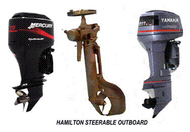
Steerable
Thrusters - (other names azimuth thrusters, Z pellers,
duck pellers, variable angle kort nozzles) are a propeller driven by a vertical
shaft through bevel gears in a housing. The housing and propeller rotate as
one. This is so that propeller thrust can be directed either side of the
longitudinal centre line of the vessel. In tugs and some special purpose ships
this can be rotated through 3600 to provide exceptional manoeuvring
ability. Other advantages are found in limited transverse thrust and greater
protection from ropes/debris fouling the propeller.
Voith Schneider Propeller - is a vertically rotating device. It has
vertical blades of aerofoil section located around a disc. The blades can be
rotated by cams and the angle of the blades determines the magnitude and line
of thrust. The thrust can be in any direction.
Pleuger
Active Rudder - comprises an electric motor driving a small
propeller in a streamlined housing built into a normal type rudder. The steering
gear turns the rudder. The thrust of the small propeller in line with the
rudder blade applies a turning moment to the ship. This is independent of the
ship's movement or the action of the main propeller. The motor operates wet in that it is water filled and the
windings are suitable for continuous immersion. All bearings are water
lubricated.
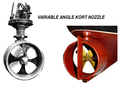
5.3 Steering
systems
Direct drive systems
Wire & pulley, Chain & drum - a wire, cable or rope is wound around a
steering drum at the wheel then passed through a series of pulleys on each side
of the vessel to drive the tiller or quadrant
of the rudder mechanism. The quadrant spreads the load at the cables attachment
point with the rudder stock. To avoid excessive strain and bending of the wire
the pulley blocks should be as large as practical, positioned to avoid
excessive angle and kept tight. Buffer springs are provided on both port and
starboard to prevent violent recoil of the steering wheel. All components
should be regularly inspected and greased or oiled.
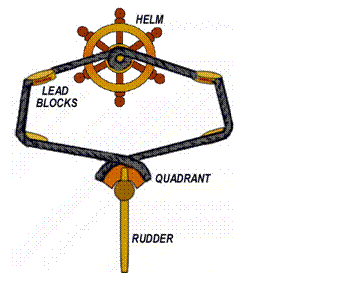
Push-Pull
Cable - This arrangement is commonly adapted for
outboard motors. The cable should not be too long or too short as this can
affect the tiller response. In case of cable or rod seizing, it must be
possible to release the push-pull rod (rack) from the tiller to operate the
emergency steering.

Chain
and box – These composite installations that are
common in older small fishing vessels make use of automotive parts such as
shafts, universal joins and truck steering boxes (differentials) and are
consequently highly individual and often over engineered for their re-birthed
use. There are many intermediate bearings and alignment can be problematic.
They require periodic inspection, lubrication and adjustment, particularly the
chain which is liable to stretch and is often adjustable.
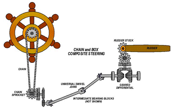
Hydraulic steering systems
Hydraulic systems become common in vessels over 12 metres in length. They range from simple manual types in smaller vessels to very complex electro-hydraulic ones. The principle however remains the same, that a flow of pressurised hydraulic fluid (oil) is directed through a ram to control the movement and position of the rudder.
They have a reservoir to hold a reserve of oil to feed the hydraulic pump. It may also cool and settle the fluid. Stainless or synthetic gauze mesh filters remove larger contaminants and a filter condition indicator may be provided to give an indication of its state.
A two way hydraulic pump, (internal gear pump or vane pump) is linked to the helm. Piping leads fluid from the pump to the hydraulic cylinder and ram, this in turn is connected to the tiller. The rotation of the wheel forces oil from the pump to one side of the ram thus rotating the rudder. Direction, check and one way valves control the fluid path. Relief valves (regulators) reduce the pump pressure to a safe level and a bypass circuit is included to enable change over to emergency steering. Force, leverage, and movement can be altered by changing the sizes of rams, gears, ratios, and linkages. The major problem associated with any hydraulic system is air (a compressible gas) entering the system so most systems are built to be self purging of air.
Survey
requirements - Steering
systems must comply with the following requirements:
Have a quick change over from the primary to the secondary
steering.
Have a
relief valve in systems with a power pump to prevent damage to the steering
gear. Hydraulic pumps shall have pressure relief protection
on the discharge side. Such pressure relief protection shall operate in
a closed circuit.
Hose
and piping must be installed to minimise mechanical, fire or other damage.
Mechanical
damage includes chafing, crushing and holing.The materials of hydraulic pumps,
motors and accessories shall be compatible with the hydraulic fluid. Hydraulic
fluid shall be non-flammable or shall have a flashpoint of 157ºC or over.
Nylon tubing may be used in hand hydraulic applications on
vessels provided it meets the requirements of AS 3791 or an equivalent national
or international standard and;
Is stabilised against degradation due to exposure to
ultra-violet light;
Is only used where suitable for the application;
Has a pressure cycling resistance equivalent to that
required for hoses to AS 3791
Does not pass
through a space designated as a high risk or machinery space or is adequately
shielded from fire within such a space (see
Part C Section 4: Fire Safety NSCV).
While
the National Standards for the Administration of Marine Safety specifies survey
schedules (see Chapter 1.2), some authorities have incorporated NSCV into USL.
Section 14 of the USL Code specifies the survey items required for currency of
a Certificate of Survey over a vessel’s life. For steering systems including
emergency steering these are:
All vessels - At the initial survey during construction
the survey of the steering gear and emergency steering gear is required. As
such equipment is new this survey would normally be confined to operational
tests to ensure the gear performs satisfactorily.
At each annual survey - An operational test of the main and
emergency means of steering.
Eight yearly survey - Test
of electrically or hydraulically operated steering gear.
Ram Arrangements - As the ram extends or retracts it moves the tiller in an arc requiring the ram to pivot at its fixed end. Clearance is needed for the sweep of the tiller and ram and linkages must provide sufficient flexibility for this movement.
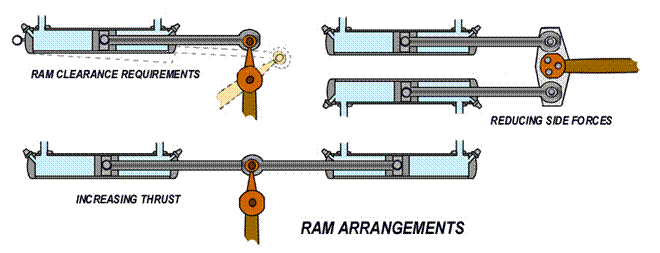
Dual cylinder installations can increase the steering torque on the rudder, however large hydraulic side-force can be exerted on the rudder-post, especially at the extremes of the rudder stroke, with single rams or double rams fitted in opposition. Arrangements to cancel side forces will utilise two double-acting rams, one pushing, the other pulling, both from the same side from a fixed rudder stock head plate.
Direct hydraulic steering (hand-operated)
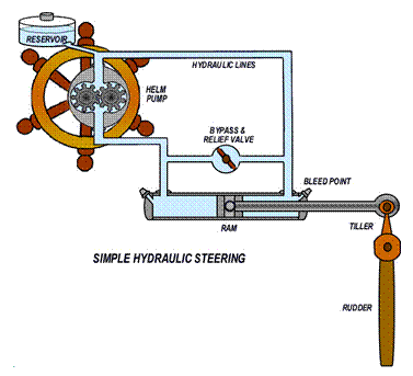
The
emergency steering will require the fluid to be by-passed and a valve is placed
between the two sides of the system for this purpose (bypass valve). To prevent
hydraulic locking, this valve will need to be opened when the emergency system
is to be operational. In addition, there should be a relief valve (bypass &
relief shown as one above for simplicity) which spills the oil from one side to
the other in the event of shock loading to the system from a rogue wave. Specific
maintenance requirement for this system is to ensure that the oil level is
adequate and that there are no leaks.
Twin helm station hydraulic steering (hand-operated)
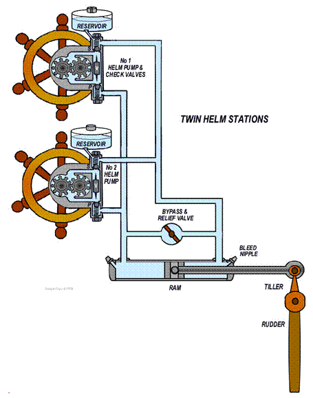
Check valves direct control to the helm station being operated. As the upper wheel is turned clockwise (to starboard), helm pump No1 pushes oil up into the top oil passage and forces the ball valve (S) to lift up from the seating against its spring. Thus oil flows outwards towards the steering ram. Simultaneously spool valve (V) is forced downward and its stylus pokes the lower ball valve (P) away from its seating, so allowing return oil to enter the pump.
The pressure of oil flowing out from helm pump No1 also acts against the back of the ball valve in helm pump No 2 and hence keeps it closed tight against its seating.
Power assisted hydraulic systems
In the example shown below a manual helm pump operates a servo ram to initiate a power assisted starboard turn (flow from the power pump through a directional valve). Thus hydraulic pressure from the power pump (electrically driven or by the vessels motor) assists the operator to activate the tiller and rudder. If the power assist pump fails, manual steering remains, but extra effort is needed. If the automatic pilot pump (electrically driven) is operated, the back pressure toward the manual helm pump bypasses the manual section of the hydraulic circuit.
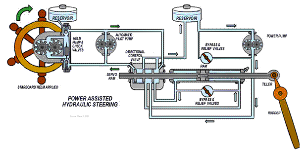
Typical power assisted hydraulic steering components from a variety of systems include:
Oil reservoir- The helm pump and header tank are often combined to form the one unit.
Helm
pump - A reversible pump driven by the
steering wheel attached directly or by chain. If drive shafting protrude from
the pump, oil seals are fitted.
Dual
helm pumps- Check valves (lockout) located
in the helm pump bypass the second helm when not required. If not fitted, operating one pump would cause
the other to move.
Rudder
indicator- Situated by the steering wheel
to indicate the position of the rudder.
Oil
lines- Typically of copper and fitted
between pump and flexible hoses at the rams. Positioned for security against to
mechanical impacts, no or only a few joins in visible/accessible positions are
a permitted.
Servo
ram- So called to distinguish from the
power ram. Oil lines connect to both ends of the ram. Bleed valves are fitted
to facilitate removal off air trapped in the system. Through the ram with
sealing rings passes a piston rod that activates a directional control valve.
Directional
control valve- It is activated by the
manual pump to direct the flow of oil from the power pump to either side of the
power ram dependant on the direction steered. It consists of a number of ports
and a spool running through the centre of it.
Hydraulic
power pump reservoir- It fills the power system
with hydraulic oil and tops up the system if there are leaks. It provides
expansion room for oil due to temperature change.
Hydraulic
oil pump- It is driven by the main or an
auxiliary engine and is a gear or vane type pump (positive displacement type
pump) and is fitted with a relief valve.
Pump
relief valve- Normally in the closed
position, it protects the positive displacement pump in case of system
blockage/overload. (A bypass may be fitted for manual operation with emergency
steering)
Non-return valve - (Not shown in the drawings for simplicity). May be fitted between the power reservoir
and pump to allow oil to flow to the suction side of the hydraulic oil pump but
not allow the oil returning from the power ram to directly enter the reservoir
Flow
control valve - (Not shown in the
drawings for simplicity). Fitted between the hydraulic oil
pump and the directional control valve to maintain regulated oil flow.
Power
ram - One end is swivel mounted. The piston
rod is driven by the servo ram and drives the tiller arm through a clevis and detachable
pin (for release to engage emergency steering). Oil lines from the directional
valve are connected to each end of the ram. A bleed valve is fitted to each end
of the ram to remove any trapped air.
Flexible
hoses - Flexible hoses are fitted between
the oil lines and hydraulic and servo rams to allow for their swivel movement.
Power
ram by-pass valve - Normally closed, it is
situated between the two oil lines by the power ram. It is opened when the
emergency steering is used to allow oil to by-pass the helm pump making it
easier to operate. A relief valve will also be fitted to protect the oil lines
from bursting if overloaded from rogue wave action on the rudder.
Tiller
arm and stops- May be attached to the
rudder stock by a key and clamping arrangement enabling mechanical advantage by
lever action. They are fitted to stop the rudder from moving more than 35º from
the centre line as steering becomes less effective over this deflection and
hydraulic system could become overloaded. They also prevent the rudder from
fouling the propeller when the vessel goes into astern propulsion.
Auto
pilot- Solenoid (electro-magnetically
operated) valves operated by the auto pilot may be attached to the directional
valve. If the vessel deviates from course, the gyro/electro compass of the
auto-pilot operates a solenoid valve to allow hydraulic oil to pump to one side
of the power ram, turning the vessel back to the selected course.
Operation
of a power assisted steering system - Start up the engine (main or auxiliary)
which drives the hydraulic oil pump. When the steering wheel is turned, the
piston and piston rod in the receiver will move a corresponding amount. The piston rod forces the directional control
valve to move and line up the ports in the direction for the oil to be pumped
from the hydraulic oil pump to the relevant side of the power ram. The oil on
the other side of the piston in the power ram will return via the directional
control valve to the suction side of the hydraulic oil pump. When the piston
moves, the piston rod pushes or pulls the tiller arm. The tiller arm being
attached to the rudder stock causes the rudder to move.
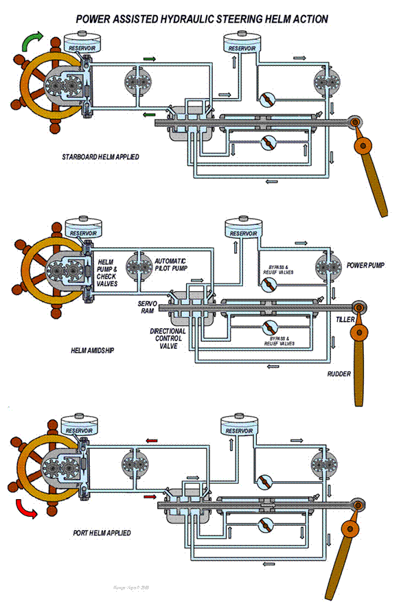
Simple
Telemotor - In many larger systems the signal from the
steering wheel is transmitted to the steering gear by means of a telemotor (a remote activating
transmitter and receiver). This not only ensures that the steering system is
isolated to the steering flat, but that the steering system can be used even if
the wheel and connections are damaged or become inoperative.
The
telemotor shown below consists of a transmitter in the wheelhouse and a
receiver in the steering flat. The movement of the wheel activates a hydraulic
piston in the transmitter. The fluid displaced by this piston is used to
displace a similar piston in the receiver. This activates the switch of a
bi-directional electric pump that in turn operates a power hydraulic pump and its
steering ram, tiller and rudder. The receiver is usually spring loaded so that
the steering wheel will easily return to the amidships position. A floating
lever and hunting gear provides a feedback loop to switch off the
bi-directional pump when the degree of helm applied matches the deflection of
the tiller.
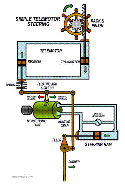
In the drawing
shown above, when the helm is turned to starboard the
telemotor (upper hydraulic circuit) transmitter piston is wound downward
causing the receiver piston to be forced upwards pulling with it the floating
lever. The upward movement of left hand end of the floating lever operates the
pump switch attached at its central pivot point. In this case the switch turns
the bi-directional pump into forward (clockwise) motion and oil is pumped into
the top of the lower hydraulic circuit. The lower steering ram piston forces
the tiller to move to the left and results in starboard helm at the rudder. The
hunting gear attached to the rudder head provides feedback to the floating arm.
It moves upward as the rudder steers to starboard and balances the movement of
the floating arm to return the switch to the off position, thus maintaining the
degree of starboard helm determined by the steering wheel.
Split telemotor steering systems -
Charging
a telemotor system - Ensure the lines are clear by blowing them
through with compressed air and clean them with a liquid compatible with the
charging fluid. The steering wheel should be amidships and receiver disconnected
from the steering gear.
A
small tank and charging pump is usually located in the steering gear space. Fill
the wheelhouse reservoir/pump tank with oil. Ensure all the valves including
bypass valve at the transmitter are open. This is to ensure that there is a
complete circuit from the charging pump through one side of the receiver ram,
one line to the transmitter back through the other line to the receiver and
return to the charging tank. Commence pumping. It may be necessary to close the
reservoir/pump valve in the wheelhouse to prevent the tank overflowing.
When
oil starts to return to the charging pump tank, vent the system via valves (air
cocks or plugs) on transmitter and receiver. They should be opened in turn to
release any air then closed. When a solid discharge (spurt) occurs at the
return pipe to the charging pump tank that coincides with the stroke of the
pump shut the charging valves.
Return
all valves in system to the working position. The steering wheel should be
turned both ways a number of times and vent valves opened on receiver and
transmitter until all air is eliminated from the system.
Electro-Hydraulic
-The electro-hydraulic system, shown below,
has the advantage that the signal from the wheelhouse to steering flat is
electrical. The system also uses a uni-directional pump which is less complex
and cheaper than a bi-directional. This pump supplies oil at a
constant rate to a directional control valve in the steering flat.
The
valve has three positions that control oil supply to either side of the double
acting ram. When in the neutral
position, oil is locked in the ram, thus maintaining the given rudder angle,
whilst the pump flow is circulated back to the tank. The valve is operated by solenoids controlled
from the wheelhouse via the control box.
As in
the previous system there is a by-pass and a relief valve fitted between the
left and right sides of the ram.
Emergency steering can be carried out by operating the emergency
steering lever located in the steering flat.
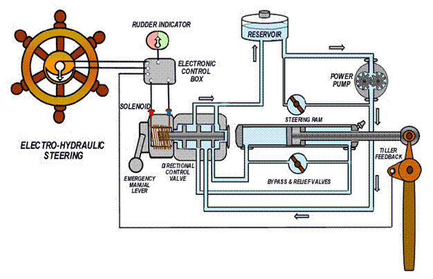
Auto pilot components and feedback mechanisms - An automatic pilot (auto pilot) is often incorporated in the steering console. It has a tiller position sensing unit in the steering flat to take the signal sent from the console and provide feedback to the auto pilot. The manufacturer’s instructions should be followed as units vary widely, but systems are generally arranged so that when the vessel is on course, the rudder is amidships. When the compass signals an error to the auto pilot (resulting from a drift off course), it applies a sufficient amount of rudder to compensate and to bring the vessel back on course. The feedback loop from the rudder to the auto pilot uses the hunting system principle described earlier in the telemotor section.
Emergency
steering
The USL Code and NSCV require all except
twin screw vessels to be fitted with two effective independent means of
steering, the second intended for emergency use. NB: Twin screw vessels do not require an
emergency steering arrangement as the vessel can be steered by altering the
revolutions of each engine.
The performance requirements for emergency steering gear are that it shall be capable of being brought speedily in to action and include communication system as required. In small vessels the operation by an emergency power source is unlikely. Common methods of providing emergency steering include:
Manual
over-ride - Normally, there is only one hydraulic oil
pump. Should this pump or the power source driving this pump fail, the receiver
operated by the steering wheel can take over through the directional control
valve. Should the failure be in the helm pump or servo ram, the manual override
can be set on the directional control valve, to allow assisted steering of the
vessel.
Where power steering is operated using a hydraulic ram -on power failure the power system can be isolated and with the ram’s equalising valve open.
Where an emergency hand operated pump is fitted but normally remains isolated from the rams - the pump is temporarily linked into the hydraulic circuit and the ram operated by the hand pump. Oil to rams is controlled by directional valves.
Emergency
Tiller Arm - Should a failure occur in either the power
ram or the oil lines and flexible lines attached to it, the emergency tiller
arm can be used. With the by-pass valve open and or the ram disconnected, the
vessel can be steered via the emergency tiller arm.
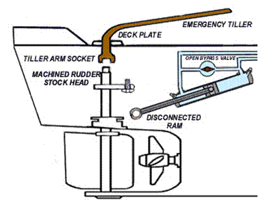
The rudder stock is extended beyond the normal tiller attachment point and is machined square on the top. An emergency tiller arm goes through a plugged hole in the deck and fits over the square. It may be located in the steering flat dependent on the available room. When not in use a watertight cover is secured over the hole. To provide additional mechanical advantage this system can be combined with a rope block and tackle system as discussed below.
Rope Block Steering - Direct tiller control can be gained by using twin rope blocks and tackles that are shackled to the tiller head and hauled from points made fast on either side of the vessel. Steering is effected by tightening one block and tackle while loosening the other (to pull the tiller one way and slacken off in the other). The ram by-pass valve must be open.
Use of drogues - In the worst of scenarios of the rudder being completely jammed or lost altogether, then twin warps and drogues with tripping lines could be streamed behind the vessel to enable a directional steering pull to the side under strain. In any but the smallest vessel the forces will be very large and hard to manually handle. An alternative may be to stream a single drogue and warp that can be hauled from one side of the vessels stern to the other with the assistance of blocks and tackles.
In
all the systems listed above, due to the limitation of power, the vessel will
probably not steer well at full speed except on a direct heading (with rudder amidships
and minimal torque). When the vessel is
turning, the torque on the rudder increases with its angle from amidships. If
the torque is greater than the manual effort that can be applied, the ship must
be slowed down to a speed at which the rudder can be controlled.
5.4 Troubleshooting
Pre-departure
checks
Sudden
loss of steering in close quarters to other vessels or in heavy weather could
be disastrous. The need for a consistent maintenance program to avoid such a
situation is self evident as summarised in the NSCV and the USL Code.
If
the vessel is fitted with an automatic pilot the manual steering shall be
tested after prolonged use and before entering areas where navigation requires
special caution.
Before
departure the vessel’s steering systems shall be checked and tested including the
full and accurate movement of the rudder, visual inspection of all parts and
linkages, the operation of the means of communication between the wheelhouse
and steering gear compartment. Simple operating instructions and a block
diagram should be permanently displayed in the wheelhouse and steering gear
compartment. Emergency steering drills shall take place at least once every
three months. Details of all tests, checks and emergency steering drills shall
be recorded in the log book or the vessel record book.
At
the helm - Rudder movement must be no
less than 35° to port to 35° to starboard. With all steering systems the steering
wheel should be capable of a turn hard over to port (35º) and then hard over to
starboard (30º) within thirty seconds to meet NSCV requirements (NSCV vessels
over 15 metres). The movement should be smooth and unimpeded and be monitored
by a correctly reading helm indicating gauge.
With
sprockets and chain steering check the attachment linkages and the chain
tension - lubricate as required. Communication equipment (radio) should be
ready in case the emergency steering needs to be deployed from the tiller flat
(stern steering compartment).
With
hydraulic steering look out for spongy feel to the steering that may indicate
air in the system. Check for oil leaks where the two oil lines connect to the
helm pump and the oil seal on the at the pump shaft. You may have to top up the
helm pump oil reservoir, so follow the manufactures instructions and use the
recommended type of hydraulic oil.
In the steering compartment - Check the flexible hoses are not perished,
cracked or leaking, especially at their connections. Check the hoses are not
too short (as they may pull out of their connections) on a turn or too long (as
they may kink or foul). The hoses should be protected from chaffing and all
connections should be free of corrosion. Check the hydraulic oil
pump if power assisted steering is fitted.
Then start up the hydraulic oil pump and have the crew turn the wheel to watch the movement of the hoses, receiver, ram and tiller arm. Watch out for oil leaks at the connections of the flexible hoses, the seal on the servo and power ram, the servo and power ram bleed valves , the connections and seals of the directional control valve and the connection and seal of the hydraulic oil pump and at the relief and by-pass valves. There should be no bulges in any of the flexible hoses. Check that the manual override on the directional control valve is operating. All locking arrangements must be in place and tight.
Check
for excessive wear (movement) in the clevis pin or hole in the tiller arm. Excessive
wear (otherwise hidden) may be detected when the direction of the steering
wheel is reversed, as in the hole in the tiller arm is hidden by the arms of
the clevis. The wear can be detected when the steering wheel is reversed as the
piston rod will move immediately while the tiller arm will remain stationary
until the excess wear is taken up. Check that the tiller arm stops are
effective, that the tiller arm is securely attached to the rudder stock and
there is no sign of wear.
Check
that the rudder stock gland shows no sign of excessive leakage (a small drip is
acceptable to lubricate the gland packing). On some vessels the rudder stock
gland may be above the water line and the packing in the gland tends to be
ignored and in time becomes ineffective. When the vessel’s stern drops, water
will pass the gland packing and enter the vessel.
Ensure
that ropes, fishing nets, drums, and any other equipment are stowed so they
cannot foul the operation of the steering gear system.
Confirm
that the emergency tiller arm is on board, readily available and that the
communication equipment should be ready in case the emergency steering needs to
be deployed.
Common faults of
steering systems
Steering
systems are reliable and faults generally arise from lack of regular inspection
or, poor maintenance.
Common
mechanical steering faults
Corrosion of parts in steering compartment - Steering gear in smaller vessels are located
in enclosed spaces where the atmosphere is damp and humid and may lack adequate
ventilation. Condensation or water in the compartment will cause corrosion that
can cause parts to seize up over time and the effects may even be noticeable
between daily checks.
Wear and linkages coming loose - Being located over the propeller and rudder,
steering components are subject to shock and vibration. This can result in nuts
becoming loose, fractures in welds and excessive wear. Chain steering needs to
be tightened regularly.
Common
hydraulic steering faults
The following steps should be followed to
prevent and correct steering gear faults- Oil should be maintained to the correct
level in the header tank using the correct grade oil recommended by the
manufacturer. The oil must be free from impurities or seals and piston rings
can be damaged allowing leaks to develop. The oil must also be free from
moisture otherwise corrosion may occur internally. Any leak should be attended
to immediately.
The
relief valve setting must only be altered to the manufacturer’s installation
instructions. Grease all linkages where required and clamp oil piping to
prevent vibration.
Air in the steering gear system - Hydraulic oil is not compressible so the movement
of the steering wheel will result in an immediate movement of the rudder. Air can
be compressed so if trapped in a hydraulic system will not transfer immediate
movement of linkages. The presence of air in a steering gear system results in
a spongy or jerky operation. This can be felt at the steering wheel or seen at
the piston rod and tiller arm.
Excessive
air enters the system when it is initially filled and can also enter the system
where the oil can leak out, such as seals on the helm pump and servo ram,
flexible hose connections, oil line connections to the helm pump, or at the
bleed, relief and by-pass valves.
Removing Air from the Steering Gear System -
Operation of the system by turning the
steering wheel slowly will cause the air to make its way to the end of the line
in the direction that the oil is being displaced.
As
the oil reaches the helm pump, the air will separate from the oil and go into
the air space above the oil in the header tank. At the other end of the oil
lines, the bleed valve on one end of the servo ram will have to be opened while
the oil is being delivered until bubble free oil is released. Should the
steering wheel be placed hard over before bubble free oil is released, the
bleed valve will have to be closed while the steering wheel is returned to the
amidships position. The procedure would be repeated until bubble free oil is
released.
If
the air enters the hydraulic oil pump/power ram lines, oil can be bled by
starting the pump and operating the manual override. Oil will flow to one side of the power ram
and through a bleed valve until bubble free oil is released. Repeat the procedure for the lines on the
other side of the power ram.
In
twin helm station setups the lower helm station is usually bled before the
upper helm station.
Chapter 6: Gears, Shafts and Propellers
6.1 Gears and clutch mechanisms
Gearing is used in drive trains (sets of intermeshed gear wheels) to alter direction, position or speed/mechanical advantage of propulsion and auxiliary equipment such as winches, pumps and steering. The gear and shaft driven directly by the motor can be called the input and the final gear and shaft it drives can be called the output. Drive train A shown below illustrates reduction and reversal of the output, drive train B illustrates reduction only with further displacement (to the right) of the output, drive train C illustrates reduction and splitting into two outputs.

Principles of marine gear boxes
The efficient crankshaft speed of a small high speed motor is greater than the efficient speed of a propeller that revolves in relatively dense salt water. The solution to this is to use of a drive train with an input shaft and drive gear wheel enmeshed with a set of follower gear wheels connected to an output shaft (a gear box). The output shaft follower (to the propeller) has more gear teeth than the input shaft driver (from the crankshaft), and therefore it rotates more slowly. The number of teeth in each gear wheel has a direct relationship to not only the speed of the follower but also the transfer of torque. The reduction ratios shown in the drawings above are calculated by the:
number of
gear teeth (cogs) in the large wheel = 16
=
2 or
a Reduction Ratio of 2:1
number of gear teeth in the small wheel 8
Therefore if the engine speed is 1000 rpm and the propeller speed is 500 rpm then:
rpm of the
engine = 1000 = 2 or
a Reduction Ratio of 2:1
the rpm of the propeller 500
While the speed has been halved, the mechanical advantage has been doubled (not allowing for efficiency losses due to friction and heat). Marine gear boxes are designed to reduce the speed of the propeller shaft but some applications require a greater speed from the output shaft. This is simply achieved by using a smaller follower to give higher output speed with less mechanical advantage. It must also be noted that by adding a following gear wheel it will turn in the opposite direction to its driving wheel (in reverse).
Gear selection and engagement
Gear box arrangements to select reverse gear include mechanically (using a gear lever directly or through a cable or linkage), electro-mechanically (using electrical solenoids which change the gears directly or hydraulically through clutches) or by hydraulic operation alone. The gearbox control and engine throttle (speed) may use separate levers for thrust and speed, or be combined in a single control lever as drawn below.
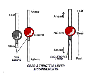
Marine transmission systems are heavy and generate considerable momentum so changing gear is smoothed by clutches. To avoid clashing of gears and overload on clutches the sequence of changing requires a delay for the propeller and shaft to slow down. Modern systems operate sequentially, or have override safety systems, however good practice remains to follow the manufacturer’s instructions always.
Clutches
In most operations it is convenient to be able to positively engage and disengage an input shaft from an output shaft. The mechanism that smooths this operation is called a clutch.
Dog clutch - The simplest arrangement as found on windlasses and winches is the dog clutch. Shown below, a collar is splined to the driving motors shaft that can be pushed by the clutch lever to engage hard against a lug in the winch drum’s side. This arrangement only allows engagement when winch and motor are stopped or both moving slowly at the same speed (a neat trick if at all possible for the arrangement shown below).

Cone clutch - The cone clutch does allow for engagement while the motor is running and is suitable for slow running operations such as capstans, windlasses and winches.

The warping drum (rope carrier) or gypsy (chain carrier) is machined with a tapered central hole. The drum is fitted over a matching tapered axle and can revolve smoothly when in the disengaged mode. The tapered axle can also be turned by a directly fitted motor. When the drum is tightened down onto the axle it grips (engages) and will turn with the motor driven axle. The system can snatch as it engages and although usually of heavy duty build, as with all friction type clutches there will always be momentary slip before engagement resulting in heat and wear.
More sophisticated systems are held in engagement with a heavy coil spring that can be manually compressed to disengage the drum from the axle. For a better grip the driving axle may be machined to mate inside a wide tapered drum and the mating cone’s surface be coated with a friction lining material.
Centrifugal clutch - A driving shaft and output coupling drum can revolve independently at their common bearing. The driving shaft has hinged weighted friction pads that at rest are restrained clear of the drum’s surface by springs. When the driving shaft is revolved the friction pads are thrown outwards by centrifugal force sufficient to overcome the springs and bind onto the drums surface (engaging the coupling). Light duty pumps and power tools often use a centrifugal clutch for its light weight and economy.

Double de-clutching - Before the modern synchromesh gearbox the earliest motor cars used a crash gearbox. To change gear, a lever is first applied to rip the currently engaged gearwheel away from the output gear train and into neutral (disengaging the engine from
the road wheels). While temporarily in neutral the accelerator is revved to boost the engine speed to match the speed of the lower gear wheel (determined by the road wheel speed). This is called double de-clutching. When the driver judges that the speeds are matched the gear lever is applied to enmesh the lower gear by crashing it into the engine gear wheel, with hopefully not too much crunching of the gear teeth.
Single plate clutch - a clutch plate disc is held firmly squeezed by heavy duty springs between friction pads on the flywheel and on the pressure plate disc.
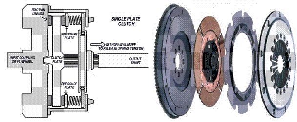
A sliding muff coupling can be withdrawn using a lever mechanism to release the spring tension and enable disengagement. Not shown in the drawing for simplicity are the photos of the flexible links between the clutch plate and the output shaft that allow for shock loads and natural oscillation in engine output.
Multiple plate clutch - The single plate clutch mechanism operates externally of the gear box and is typical for auto applications. For weight and space saving, marine applications usually have clutches that operate within the gear box. The large single clutch plate is replaced by several smaller ones enabling equivalent surface area contact in a more compact unit.
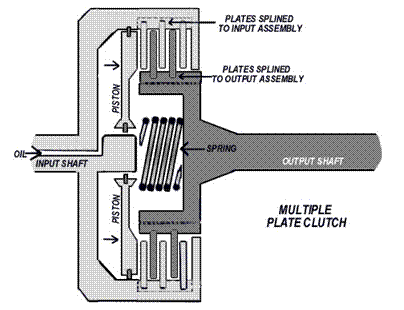
Hydraulic
oil is pumped in through the input shaft which forces the internal piston disc
to overcome the hold off resistance of the return spring and move towards the
output assembly. This in turn squeezes
together the plates that are alternately splined (embedded) inside the rim of
the input shaft assembly and on the outer rim of the output shaft assembly.
Adjusting the hydraulic pressure enables accommodation for heavy loading
operations as may be required for low gear or reverse gear.
Clutch slip - Clutch slip describes when there is incomplete engagement between the driving and driven side of the clutch. The power developed by the engine is therefore not fully transmitted to the propeller. Wear of friction plates or linings is unavoidable due to momentary slippage when clutch is being engaged. Each engagement results in a slight loss of the friction material. In the course of time, this accumulated wear allows slippage. With regular maintenance, adjustments can be made to the clutch to reduce this problem but eventually wear will be such that the friction material will need to be replaced.
Fluid (hydraulic) coupling – while a hydraulic linkage may be the activating mechanism to enable positive engagement in the previous clutch types, the fluid coupling transfers thrust by smooth fluid action. Consider a household electric fan pointed towards another. The second fan will slowly rotate in the breeze. This induced motion in the driven turbine (second fan) enables a cushioned engagement/disengagement between a driving motor shaft and a driven shaft albeit with some slip (poor thrust transfer) at low speed.
A fluid coupling transmits rotation from one shaft to another by accelerating hydraulic fluid inside its housing containing closely fitted rotors; the input driving shaft pump (impeller) and the output driven shaft turbine (runner). The flywheel, impeller and housing (shell) are fixed and the cavity filled with hydraulic fluid. The impeller spins the fluid from the centre where the velocity is low, to the periphery where the velocity becomes high. A net force of multiplied torque on the turbine causes it to rotate with the direction of the impeller.
Fluid couplings have a stall speed where the impeller is turning but not
fast enough to coax the turbine into rotation (i.e. when the car driver stopped at traffic lights
selects the gear while his brakes are still on). In this condition for
excessive periods or if the runner becomes jammed, the engine's power could transfer
its energy as overheated fluid, possibly leading to damage. A fluid coupling only
achieves about 94% transmission efficiency due to fluid friction and
turbulence.
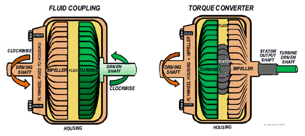
Torque
converter - Unlike the two
rotor fluid coupling, the torque converter has at least three rotors- the
impeller (motor driven), the turbine, (load driving) and positioned between them the stator (that
modifies oil flow returning from the turbine to the impeller).
The fluid flow
returning from a fluid coupling’s turbine
can oppose the direction of impeller rotation during slip, causing lost
efficiency. The torque converter uses its stator to redirect the returning
fluid to assist the rotation of the impeller so improving efficiency and output
torque. Though simple stators can be fixed often they are mounted on a one
way clutch allowing forward
motion only. Since the returning fluid is initially travelling in a direction
opposite to impeller rotation, the stator will likewise attempt to
counter-rotate as it forces the fluid to change direction, an effect prevented
by the one-way stator clutch. The typical torque converter in automatic transmissions
has three stages of operation:
Stall- the motor turns the impeller but the turbine cannot
rotate. (When the car driver stopped at traffic lights selects the gear while
the brakes are still on).
Acceleration-the motor accelerates with the impeller spinning at
a greater rate than the turbine.
Coupling-The turbine has reached approximately 90% of the
speed of the impeller. Torque multiplication has ceased and the torque
converter is behaving like a fluid coupling.
Lock-up clutches
such as the Voith TurboSyn coupling overcome the problem of
slip and improve fuel efficiency by coating the periphery of a multi-section
impeller with friction plates. Centrifugal force throws the impeller onto the turbine
at higher revolutions, creating a positive clutch lock at speed.
6.2 Reverse and reduction
gear boxes
The gear system below has an input shaft and forward shaft (often combined), a reverse shaft and an output shaft turning within an oil bath called the sump (not shown). The forward and reversing shafts have pinions (driving gear wheels) engaged by clutches. When disengaged as below the reverse pinion gear wheel rotates freely on its shaft.
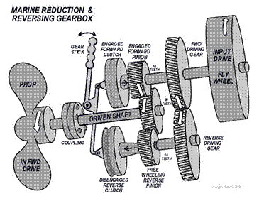
Ahead
mode operation - The forward clutch pushes the forward pinion
to engage on the forward/input shaft. The forward pinion then drives the driven
shaft as shown above. The reverse clutch is not active so the reverse pinion rotates
freely on the reverse shaft.
Astern mode operation - The
reverse clutch pushes the reverse pinion to engage on the reverse shaft. The reverse pinion then drives the driven
shaft as shown above. The forward clutch is not active and the forward pinion rotates
freely on the forward/input shaft.
An input shaft driven oil pump provides oil flow for lubrication and operation of the clutches. Oil pressure is regulated by a pressure relief valve before distribution to the gears, bearings, clutch and control via passages in the gearbox. A control box is mounted on the top of the gearbox and connected by linkage (electronic, hydraulic, pneumatic) to the throttle and forward/reverse control at the wheelhouse and gearbox (for manual emergency operation). An oil cooler and oil filters may be mounted on the gearbox.
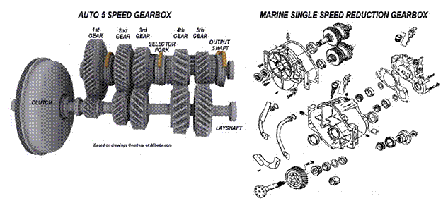
Epicyclic or planetary
gearing
Epicyclic or planetary gearing systems provide the advantages weigh saving, balance and compactness
for a gear box suitable for marine applications. Variations of three basic geared
components of a sun gear, planet gear and annulus are utilized.
One or more outer gears
(planet gears) revolve about a central gear wheel (sun gear). In more complex systems groups of
planet gears can be mounted on a movable arm (carrier) which as a body
can rotate around the sun gear. An outer ring (annulus) with inward-facing teeth mesh with the
planet gear. In operation one of the three components (star, planet or annulus) is held stationary, another is used as a
power input and the last component is used as the output. The
ratio of input to output is dependent upon the number of teeth in each gear,
and upon which component is held stationary.
In the reversing gearbox shown below the output shaft can revolve in ahead mode (anticlockwise) with the annulus free to rotate
within the shaft. If however the annulus
is locked on the output shaft by the outer tightening collar (brake band) the annulus and shaft
are rotated in reverse (clockwise) by the planet gears.
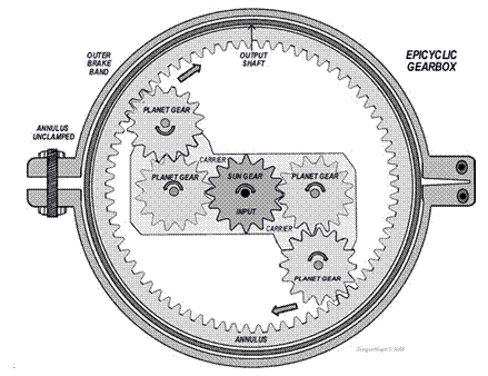
Epicyclic gear
arrangements can be simple or compound. Compound arrangements enable large
reduction ratios, weight saving and flexibility. They may be meshed-planet (at least two or more
planets in mesh within each planet train), stepped-planet
(a shaft connects two planets within each planet train), or multi-stage structures (two or more
planet sets).
Main thrust bearing
The main thrust bearing is
located on the output shaft near the aft end of the gearbox. Its function is to
carry the reaction to the thrust of the propeller and transmit it through the
gearbox casing/frame to the framework of the vessel. This ensures the gears and
engine are not affected and remain in the correct
longitudinal alignment.
Gear box
maintenance
Assuming that normal maintenance has been carried out on the gearbox, for daily pre-departure checks it should be sufficient to:
Check the oil level in the gearbox sump.
Run the engine with the gearbox in neutral
position and check for leaks.
Operate the gearbox in the head and astern
mode to ensure satisfactory operation after ensuring that the lines holding the
vessel are secure during testing.
Gearboxes are fairly reliable. Faults tend to be due to lack of normal maintenance such as:
Adjustment of clutches and operating
mechanism
Maintenance of filters
Cleaning of oil coolers
6.3 Couplings and
intermediate shaft
Muff Coupling
A muff coupling is a sleeve joining two in-line shafts. Unlike flange type couplings which butt solidly together, the muff coupling allows for a gap between the joining shafts so that expansion of one shaft (due to heating) can be accommodated. It is therefore used where one of the shafts must expand longitudinally due to heating (such as steam turbine shafts). The coupling shown below is heated and shrunk on. To remove, oil is pumped under pressure into grooves assisting release of one half of the coupling.
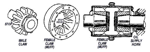
Muff Coupling
Alternative arrangements include keyed half couplings that are a press fit on shafts or half couplings that are forged integral (are part of) with the shaft
Flange Coupling
A flange is fitted to the end of a shaft and bolted to a similar flange on the end of the adjoining shaft. The flange may be an integral part of the shaft or separate from it. If separate it has to be keyed and secured to the shaft. The mating flanges are butted and bolted together using fitted bolts with accurate alignment to avoid wear on the bolts.
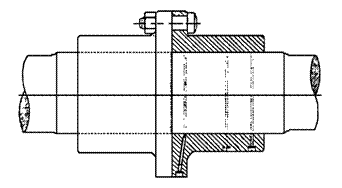
Flange
coupling
Faulty couplings are rare, the problem usually being misalignment or loose bolts, the later often created by excessive vibration from misalignment. Care should be taken in alignment adjusted on the slipway with older wooden boats as the hull may alter shape when fully supported when back in the water.
Flexible
couplings
Some flange type couplings (known as flexible couplings) have bolts that are secured in one half of the coupling and loose in the other. The loose half bolt has a rubber or synthetic sleeve which allows for flexibility in alignment. This type of coupling is often used as a less than ideal last resort where satisfactory alignment has not been successfully achieved in a marine shafting.
Checking intermediate shaft alignment
Misalignment will cause noise and vibration. Gearbox and shaft bearings can overheat and collapse more quickly. The flange couplings of the intermediate shaft of a vessel in service can be checked for parallel, concentricity and alignment using:
Dial indicators and/or
Feeler gauges and straight edges.
Utilising a dial indicator -
1.
Inspect the intermediate shaft. If supported on two bearings go to step
2. If supported on a single bearing it is necessary to provide a temporary
support to ensure the shaft does not tip. This could be a vee block set up to
ensure the shaft maintains the same alignment.
2.
Remove the coupling bolts at either end. If muff couplings are fitted,
dismantle them and slide the muff/s away from the shaft ends.
3.
Using an indicator gauge, clamp the gauge on the engine/gearbox side
half coupling. Set the pointer on the top of the intermediate shaft coupling
flange and record the reading on the indicator dial. Rotate the engine gearbox
shaft and take readings of the dial at 90, 180 and 270 degrees. For perfect
alignment, the indicator reading should remain the same at all angles. The
procedure for a muff coupling is similar except that the indicator gauge is
clamped on the shaft and the pointer set on the intermediate shaft.
4.
As a double check transfer the dial indicator to the intermediate shaft.
Set the pointer on the engine gearbox shaft and repeat the action in Step 3.
The readings should be the same as before.
Using feeler gauges and straight edge -
1.
Inspect the shaft. If supported on two bearings go to step 2. If
supported on a single bearing, provide a temporary support to ensure the shaft
does not cant or tip. (This could be a vee block carefully set up to ensure the
shaft maintains the same alignment.)
2.
Remove the coupling bolts at either end. If muff couplings are fitted,
dismantle them and slide the muff/s away from the shaft ends.
3.
Lay the straight edge across the outer diameters of the half couplings
at 0, 90,180 and 270 degrees. Any mis-alignment will show as a gap between
straight edge and one half coupling. This gap can be measured by feeler gauge.
4.
Again as a double check, rotate one of the shafts 90 degrees and repeat step
3. Allowable mis-alignment will depend on the diameter of the shaft. The
vessels operating manual or other documents will often provide the information.
Setting up for propeller shaft
alignment
The shaft coupling must accurately line up with the gearbox coupling. The engine & gearbox unit position can be adjusted by loosening its mounting bolts and adding or removing shims (metal spacers) to lift/lower the gearbox & coupling for correct tilt & elevation (alignment).
If the shaft is drawn (removed) while the vessel is on the slipway, alignment can be positively adjusted by stringing a taut piano wire through the dead centre outer bearing, the inner bearing and carried on to the gearbox flange. If the wire does not meet the dead centre of the gearbox flange then either the engine & gearbox unit must be adjusted with shims, or the outer bearing bracket moved (the latter being more problematic.)
6.4 Stern tubes
and shafts
The stern tube contains the propeller shaft, and shaft bearings and seals. The stern tube may be water lubricated, or oil-filled.
Water lubricated - The water lubricated stern tubes (as below) allows the stern tube to fill with sea water, and the shaft runs in water lubricated bushes. Some systems can also use pumped engine cooling (raw) water from the jabsco supply to inject water around the stern gland housing. A gland sealed by compressible rings of rope like gland packing material the inboard end stops too much sea-water leaking into the vessel, but some dripping is acceptable as this helps to lubricate the gland.
Some systems provide a grease nipple on the inner stuffing box. Though the grease will initially stop leaking it should be used with discretion as grit and sand can create a paste that actually wears the shaft and ultimately increases leaking. The gland can be periodically checked and tightened slightly to reduce dripping if necessary. Feel the bearing after tightening for excessive heat due to friction, and loosen if required.
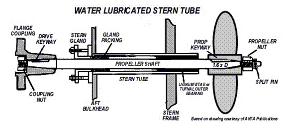
The stern gland can be re-packed as the gland packing material wears away. Dig out the old gland packing carefully to avoid scoring the bearing. New gland packing coils must be cut to the correct length from the continuous lengths supplied by your marine dealer.
Consult your manufacturer’s instructions for the correct size (usually at least three coils of gland packing sized appropriately to the shaft diameter). When cutting the coils make a diagonal cut (scarf) to increase the overlap at the ends. A minimal wipe of grease on the shaft may be acceptable to ease fitting, but don’t overdo it. Tighten the gland and monitor for heat and dripping for a few days until it settles in. Re-adjust as required.
The propeller fits tightly onto a tapered shaft and is positioned with a keyway. This keyway needs to support the propeller over 1.6 x diameter of its hub length along the shaft (i.e.
a shaft diameter 50 mm x 1.6 = 80 mm keyway).
Routine management - Check the stern gland for leakage. Though it is common practice to allow a slight leakage from the gland to keep it cool, many modern stern gland packings (due to their low coefficient of friction) will operate satisfactorily without leakage. Listen to the noise generated by the rotation of the propeller. Increase in noise generally means wear in the after stern tube bearing.
Oil-filled
stern tubes - give better lubrication and reduce corrosion. Sea-water
is kept out of the stern tube by a complex outboard seal with springs and o rings that retains the oil bath. An
inboard mechanical or standard packing gland seals oil
inside the stern tube to lubricate the white metal bearings. The stern tube
oil header tank should be regularly checked and topped up. A
pump to circulate the oil around the system may be provided and valves for
venting and draining are also provided.
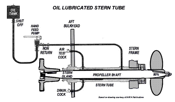
Routine management - Check header tank to ensure there is no loss of oil. Check oil for water dilution. Most oils are designed to emulsify if water enters the stern tube. If the forward gland is the packing type there should be no leakage. Adjust to stop leakage if necessary. Mechanical seals at the forward end are usually trouble free but should be regularly checked. A save all should be provided to catch any oil leakage thus preventing it from entering the bilges.
Mechanical shaft seals or PPS –The shaft is contained in an oil bath within a rubber boot and sealed with o rings running in grooves. These are often called drip-less shaft seals with the obvious advantage of maintaining a dry bilge. They are very common in smaller craft with small diameter shafts.

Outboard engines have a sealed, oil filled foot containing gearbox, bearings, shafts and seals. The oil level in the foot should be regularly checked and periodically changed as shown in the engine maintenance schedule. The differences between oil lubricated and water lubricated stern tubes include:
|
Water lubricated stern tubes - |
|
|
Advantages |
Disadvantages |
|
A tried and tested sturdy system. Simple to repair wearing parts or replace,
but usually requires dry dock for repair. No complex mechanical seals. |
High wear rates at the aft bearing and
shaft liner or shaft as it carries the weight of the propeller. Carbon steel shafts have to be protected
from corrosion by a sleeve or liner. On smaller ships the shaft is often made
from corrosion resistant steel or monel and a liner is not required. |
|
Oil lubricated stern tubes - |
|
|
Advantages |
Disadvantages |
|
The shaft runs in oil. Friction is reduced and more power is
available at the propeller due to white metal bearings. Less wear and longer life from reduced
friction. For carbon steel shafts, liners are not
required for protection of the shaft from corrosion as the shaft is not exposed
to sea water. |
Initial cost is greater as additional
piping. An oil header tank is required. After end of the stern tube requires a
mechanical seal which, to ensure reliability, is of a fairly complex design.
The forward end can be fitted with either a mechanical seal or conventional
packing gland. |
Measuring stern tube bearing and tail shaft
wear
Two bearings usually support the propeller shaft (tailshaft or shaft). One is located at the forward end where the shaft penetrates the aft engine room bulkhead and the other is at the after end of the stern tube. The forward bearing is not accessible unless the shaft is removed. As it only carries part of the weight of the shaft, wear is not usually a concern. The aft bearing has to take part weight of the shaft and the whole weight of the propeller so considerable wear takes place in this bearing. Weardown is a measure of the sag (deflection) of the shaft due to bearing and shaft wear.
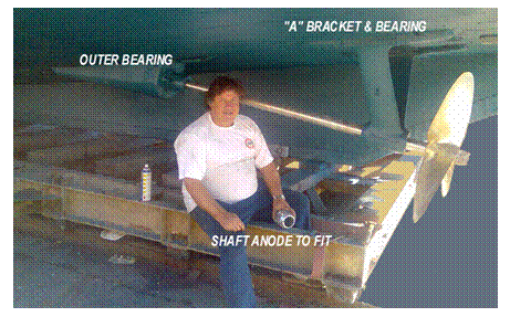
Shafts should be withdrawn for inspection every 4 years. Increased vibration at the vessel’s stern with persistent stern gland leaks (despite adjustments) are symptoms of excessive weardown. If exceeded, the consequences include fracture of the shaft with propeller loss. Weardown allowance is determined by the manufacturer, but rules of thumb range from 3% of diameter as due for replacement to 6% being condemned (3% of a 50mm diameter shaft is 1.5mm permissible movement within the bearing).
Water lubricated tailshaft wear - The aft bearing is accessible via the small gap between the aft end of the stern tube and the front end of the propeller boss. If a rope guard is fitted over this gap, it must be removed. The shaft rests on the bottom half of the bearing. The gap between shaft and stern tube bearing can be measured by using long feeler gauges inserted at the top of the shaft. Many bearings have longitudinal grooves to allow water to circulate. Ensure measurement is taken at the bearing surface not the groove. If the gap above is too small to allow access of the feeler gauges another method of measuring the weardown is to clamp a dial indicator gauge to the hull with the pointer resting on the top of the shaft between the stern tube and propeller. Note the dial reading, then jack up the prop until resistance to jacking increases. Note the new reading. The difference is the weardown (the sum of the wear in the bearing and shaft wear).
Oil lubricated tailshafts wear - These shafts can have a mechanical seals at each end. The standard method of checking wear is by depth gauge. A collared plug in the gland housing or the stern tube just forward of the gland is removed. The depth from the face of the plug boss to the top of the shaft is measured. This should be compared to the original measurement when the shaft was installed. The difference is the weardown.
6.5 Propellers
Propeller theory
|
Pitch (geometric pitch) |
The action of a propeller is similar to a carpenter’s auger rotating to drill a hole through a piece of timber. The drill digs a hole equal to the angle of the shavings clearance spiral (the pitch) of the auger with each complete rotation. Unlike the auger, a propeller is not a continuous spiral but sections from it (blades) are placed around a central hub. As it rotates in a fluid medium the hole the propeller digs in the fluid (the actual advance of the propeller) is less than the geometric pitch. The difference is termed the slip. |
|
Pitch
angle |
Ø is the pitch divided by the circumference of the prop at a given diameter. ie. Tan Ø = pitch/p x diameter of the propeller. |
|
Diameter |
Means the maximum diameter. With an even number of blades, it is the distance from the tip of one blade to the centre of the blade. Directly opposite for odd numbers, it is twice the distance from the centre of the propeller to the tip of any blade. |
|
Cavitation |
The results from pressure variations on the back (forward face) of a blade forming vapour filled cavities (bubbles). This leads to a loss of thrust/torque and increase in revolutions until the bubbles collapse. The collapsing bubbles produces intense local pressure on the blade that results in erosion and surface pitting. |
|
Excitation |
Where the natural frequency of the propeller blades is the same as frequencies derived from other sources. Examples include: the variation in torque of the engine pressure variation as a blade passes the
stern the flow of the water into the propeller the natural hull frequency The synchronised result can produce resonance in the blades and unacceptable vibration of the propeller or shaft. Sometimes the blades generate disturbing noises called a singing propeller. |
Propeller calculations
Description - Viewed from the stern of a vessel the shaft may be configured to turn in clockwise direction (right handed) or in an anticlockwise direction (left handed). Due to the differential water density and aeration experienced by a propeller’s uppermost submerged blades and the lower submerged blades, a right handed prop will create a paddle wheel effect. This pushes the vessels head to port when ahead propulsion is first engaged and pushes the vessels stern to port when astern propulsion is first engaged. The inertia of a vessel accelerating from a stall (being stopped in the water) accentuates this effect.
With twin propped vessels the starboard prop is usually configured to be right handed and the port prop to be left handed. Some props may be set up as twins on the same shaft, counter rotating to negate this paddle wheel or transverse thrust effect. The prop may have two, three or multiple blades. Consequently a propeller it is described by its number of blades, the direction it turns, its diameter and its pitch.
A four bladed, right handed, 75 cm diameter x
150 cm pitch propeller.
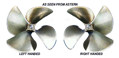
Gear and propeller ratio –The gearbox reduces the drive speed from the engine to the shaft and propeller to reduce the likelihood of excitation and slip. For an engine that turns at 2400 rpm with a propeller designed to turn at 800 rpm, the following can be found:
Gearbox ratio =
Engine speed = 2400 = 3:1 Ratio
Propeller speed 800
This relationship is also described by the formulae:
Gearbox ratio =
Engine speed = Engine ratio
Propeller speed Propeller ratio or
Engine speed =
Propeller speed x Engine ratio
Propeller ratio or
Propeller speed =
Engine speed x Propeller ratio
Engine ratio
Using a 75 cm diameter x 150 cm pitch propeller at theoretic speed (discounting slip) for every revolution it could move the boat 1.5 mtrs forward through the water. The vessel’s speed would be:
Propeller pitch x
revolutions per minute = distance travelled per minute or
Theoretical speed in knots = Propeller pitch x
propeller revolutions x 60 minutes
1852 mtrs per nautical mile
Theoretical speed in knots = 1.5 x 800 rpm
x 60 = 38.87 nautical miles/hour
1852
With a 50 cm diameter x 75 cm pitch propeller the theoretical speed for every revolution could move the boat 0.75 mtrs forward. Assuming 350 rpm prop speed:
Theoretical speed in knots = 0.75 x 350 rpm
x 60 = 8.5
nautical miles/hour
1852
The process of the vessel through the water (the apparent speed) is often measured by a log (an impeller device recording water flow past the hull). The log suffers inaccuracies due to calibration error, water flow anomalies and the envelope of water that is dragged along with the vessel’s hull (the wake). The log will read higher or lower than the theoretical speed. The difference between these two distances is called the apparent slip. For example our 8.5 knots theoretical speed read 7.7 miles on the log
Theoretical speed - Apparent speed (Log speed) = Loss/gain in speed (apparent slip)
8.5 - 7.7 = 0.8 knots Positive apparent slip
(Where log speed is less than theoretical speed it is called positive apparent slip.)
The True speed of the vessel between two points can be found from traditional position fixing or electronically by GPS or radar. The difference between the True speed and the Theoretical speed is the True Slip. The relationship of the terms is shown below:
Fixed pitch propellers
The propellers may have two, three or multiple blades of varying sizes and pitch. The aim of the ship designer is to match the engine, gearbox, shaft and propeller to enable the most efficient propulsion system for the intended trade and sea area.
All displacement vessels will have a predetermined maximum speed at the point when the movement the hull through the water creates a displacement wave matching the vessel’s underwater length. To go faster the vessel would have to climb over its own displacement wave requiring expediential and inefficient use of power. These vessels usually have shafting parallel or nearly parallel to their water line, allowing horizontal thrust from the propeller.
Planing vessels have sufficient power with flat bottoms that climb over and escape their wave of displacement to skim over the water surface. But the shaft often has to dip steeply down to reach the water, and the consequent clearance between outer bearing and the hull bottom restricts the size of propeller that can be fitted. The thrust from extreme variations of this set up can have a significant vertical (downward) component.
The selection of propellers is complex and can be aided by software calculators. General principles are that slip is reduced by a coarser pitch. High revving props and ones required for high torque operations such as towing will usually have a coarser pitch.
Controllable pitch propellers
Controllable pitch propellers have blades that rotate on their axis around the hub.
This provides a method of adjusting the pitch of the blades from the normal full ahead position to zero pitch then to full astern. With these props the transverse thrust is always in the same direction, as the shaft always turns in the same direction independent of ahead of astern propulsion. Controllable pitch propellers including folding props also allow refining the pitch for versatility in multitasking operations such as towing, trawling, sailing or making good speed back home with the catch.
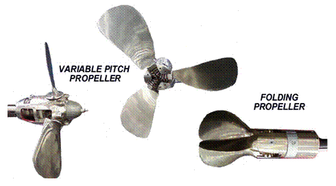
There are many types of adjusting mechanisms. Some rely on oil pressure provided by an oil distribution/control box mounted around a section of the after most intermediate shaft, or on the end of the aft end of the reduction gear. Oil pressure is generated by a shaft or electric motor driven pump. A control mechanism is mounted on the distribution box. A piston rod passing down the centre of the shaft actuates a servo motor in the propeller hub which, by means of sliders/cranks, turns the blades.
Fitting and removing propellers
Fitting a Propeller - A machined
taper of usually 1 in 12 on the propeller end of the shaft and a matching taper
in the bore of the propeller positively position the propeller on the shaft. A
keyway over a distance of 80% and key is provided in the shaft with a matching
keyway in the propeller. The small end of the shaft is extended and threaded to
take a nut. The propeller is hardened up on the shaft taper by tightening the
nut. A locking device is fitted to prevent the nut from slackening that can be
a Setscrew or Allen screw that penetrates both the nut and the propeller boss.
Often a castellated nut and split pin or cotter pin is used.
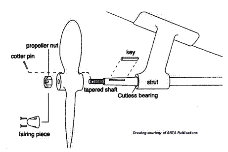
Removing a Propeller - Think safety, as propellers can be very
heavy and may have sharp edges. Always beware that as the propeller becomes
free, it can quickly slide along the shaft. You should take precautions to
ensure that the moving propeller does not fall off the shaft causing personal
injury or damage.
To remove a large propeller first fit
lifting arrangements to support the prop.
To remove a small propeller remove rope
guard and fairing piece from propeller nut, then remove locking device and nut.
The prop may be stuck fast on the shaft. That means that when it does come off
it may do so suddenly, so refit the propeller nut and tighten for a loose fit
sufficient to stop the prop jumping off the shaft when it finally becomes free.
Fit the drawing gear (two or more long studs
that screw into threaded holes) in the back of the propeller boss and a strongback. Place the strongback over the
studs so that it bears on the end of the shaft and run nuts down on studs.
Tighten the nuts to increase load on studs. At some point, the load will hopefully
overcome the friction between propeller and shaft taper and the propeller will dislodge.
If the propeller is holding, a sharp hit with a large hammer on the strongback
will often produce results. In extreme cases heat may have to be applied to
break the seal of corrosion.
Chapter 7: Marine DC electrical systems
7.1 Basic principles, units and simple circuits
Installation
and repair of electrical systems requires trained and licensed electrical
tradespersons. Even though systems may incorporate warning and disabling safety
devices, it is vital that any circuitry is isolated (turned off at source)
before opening up for inspection. This section limits itself to basic
principles sufficient that a Marine Engineer can recognise unsafe systems and
call in a licensed expert if needed. Misuse can kill.
Four fundamental forces hold our universe together - Gravity, Electromagnetism, the Strong Nuclear Force and the Weak Nuclear Force. The building block of the universe’s matter, the atom, has a central nucleus composed of particles including protons and neutrons (positive and neutrally charged) and an outer boundary of trapped orbiting electrons (negatively charged particles). A comparison can be made to planets orbiting a sun, but it is not gravity (the glue of solar systems) that stabilises the atom, but the strong nuclear force locally bonding the nucleus’s particles and electromagnetic attraction of negatively charged electrons to positively charged protons. If friction, as in the collisions of ice and water within storm clouds, causes sufficient imbalance of forces to ionise the air (strip billions of electrons from their stable orbits) an energy differential can develop between the clouds tops and bottoms. In the inevitable lightning blast electrons escape in an electric charge seeking a path of lowest resistance to earth to re-bond and stabilise.
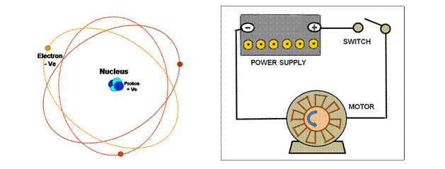
Alternatively, that charge can be harnessed within an electrical circuit. The electricity that we use to power our industry and homes uses a flow of electrons through a material described as a conductor. Metals and liquids (including human’s tissue) are good conductors, but plastic, rubber and ceramics are so resistant to electrical flow that we call them insulators. Consequently, we use metals such as copper for electrical cables and plastics or ceramics to sheath them from each other or from dissipating back to earth.
The simple electrical circuit shown above can direct current from a battery (power supply) along a conductor (the cable), through a switch and drive the electrical motor. This is an open circuit (the switch is off) so the motor will not work until the switch is turned on (closed circuit).
We cannot see the electricity, but with appropriate electrical gauges we can measure a potential difference across the battery (in units called volts), a current along the cable (in amperes) and resistance to turn the motor (in ohms). This relationship of these units can be compared with the drawing below. The top dam contains a pressure head of water (like voltage). If the tap is turned on the water flows down the pipe (like current through a conductor) and spins a water wheel below. In overcoming the water wheel’s reluctance to rotate work is done and resistance is created in the water circuit.
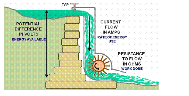
The relationship of electrical pressure, current flow and resistance (called Ohms Law), is shown in the triangle and its formulas below. If we know two of the units of measure we can calculate the other and so monitor the performance of our system (its electrical rating).
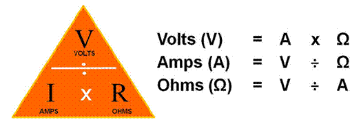
Simple circuits
In
the next circuit there is a battery with a potential of 12 volts and a load
(light globe) that when switched on will demand 2 amps to burn brightly. Conductors
resist the flow of electric current (not super conductors) and convert a
portion of the electrical energy into heat. That work done will create a
resistance to flow that we can calculate using Ohms Law - The ratio of the potential difference (volts) between the ends of a
conductor and the current flowing through the conductor is constant. This ratio is called the resistance of
the conductor and is expressed in the circuit and formula below:
Volts ÷ Amps = Resistance 12 V ÷ 2 A 6 Ω Volts x Amps = Power 12 x 2 A = 24 Watts
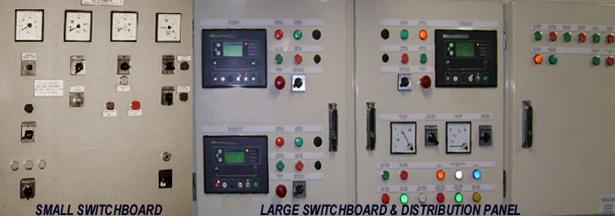
Commonly
the power consumption of a load is described by the unit called watts, where:
|
|
= |
Volts |
x |
Amps |
In
the circuit above it can be calculated that the globe rating required is 24
watts.
|
24 Watts |
= |
12 V |
x |
2 A |
Watts
(W) or Joules (P) are defined as units for
the amount of work done in one second with a potential difference of one volt
and a constant current of one ampere.
P = V x A P = A2x Ω P=V2/
Ω
In
the following diagrams:
a.)

R =
V = 1 = 1 Ω P =
V X
A = 1 X
1 = 1 Watt
A 1
b.)
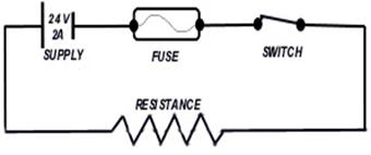
R =
V =24 =
12 Ω P =
V X
A = 24 X
2 = 48 Watts
I 2
The
circuit above includes a basic safety feature called a fuse. If the circuit is overloaded then the thin sacrificial
wire of the fuse will glow red hot, melt and break before serious damage can
occur to the circuit’s cabling. This could happen if a short circuit occurred (where the cable’s insulation is damaged and
current bypasses the globe, typically by tracking through the metal of the
vessel’s hull or other exposed conductor). Clearly, keeping the insulation of
our cables in tip top condition is a high priority for electrical safety. Don’t
drag power cords over sharp surfaces, coil too tightly or expose to
deterioration by the heat, weather or chemicals.
Series
and parallel connections are made when a large storage capacity is needed but a
single battery would be too heavy or cumbersome to handle.
Series
Circuits- If two or more batteries are connected in
line with each other, they are said to be connected in series. The total voltage
would be the sum of the individual batteries added together. While the output
voltage increases, the total amp-hour capacity of the three batteries together
remains the same as the amp-hour rating of one. In the case below the circuit
provides 36 volts at 20 amps for an hour.
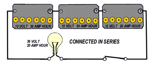
Similarly
other components such as resistors (electrical devices that create resistance)
connected in series would have their total resistance increased.
Parallel
Circuits - If two or more batteries have all their
positive poles linked and all their negative poles linked they are said to be
connected in parallel. The total voltage would as one of the batteries. While
the output voltage remains the same, the total amp-hour capacity of the three linked
batteries increases. In the case below the circuit provides 12 volts at 60 amps
for an hour.
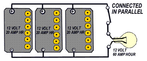
The
total power available would be:
Volts
x Amps = 12 x 60
= 3600 watts.
The
resistance of the circuit would be equal to the sum of the resistance of each
path.
From
the example above, the Ohms Law formula can be converted to:
R = 12V = 12V =
0.2 Ω
20A + 20A + 20A 60A
In
the case of three batteries in parallel, they still have the same voltage, but
there is an increase in the capacity.
This means the linked batteries could be used for three times longer
when charged but the battery with the highest terminal voltage will regulate
the charger. This means the battery with the lower terminal voltage may never
reach a fully charged condition.
7.2 The battery
Common marine rechargeable batteries
A
battery is a storage device for electrochemical energy that easily enables conversion
into electrical energy and vice versa. If two electrodes (pieces of dissimilar metals) are immersed in a cell (a bath) of electrolyte (a reactive acid or alkali) a voltage will be produced
across the electrodes. While many materials will produce a limited charge the
two most common types of battery, described by their electrode metal and electrolyte,
are the lead acid battery and the alkaline battery. In a lead acid battery (dilute sulphuric acid
and lead), each cell produces approximately 2.1 volts. A nicad alkaline battery (potassium hydroxide
and nickel/cadmium) produces 1.22 volts in each of its cells. For usefully
higher voltages these batteries need groups of cells to be connected in series.
Great care must be taken not to cross contaminate acidic and alkaline materials
in order to maintain their fortitude and to avoid explosive reaction.
Lead acid batteries
The
components of a lead acid battery cell are:.
Positive plate cathode of lead dioxide (PbO2)
Negative plate anode of lead (Pb)
Dilute sulphuric acid electrolyte (H2SO4 +
H2O).
While
undergoing a discharge cycle (battery on load) lead sulphate is deposited on
both plates and water is formed due to chemical reaction. The water dilutes the electrolyte, lowering
its specific gravity from approximately 1.26 to 1.15.
When charging, the lead sulphate is re-converted to lead dioxide on the positive plate and lead on the negative plate. At the same time ionised, sulphuric acid is formed and hydrogen and oxygen is released from the H2O. This causes electrolyte concentration and the specific gravity to return to approximately 1.26. The hydrogen emitted on charge is an explosive gas. Measuring the specific gravity of the electrolyte can therefore determine the state of charge of each cell of the battery.
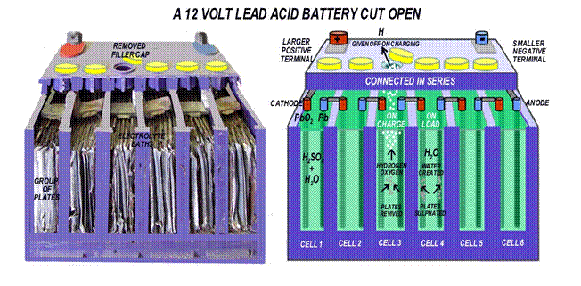
In
the battery above the six cells with a maximum of 2.1 volts are internally
connected in series to give an output of 12.6 Volts (nominally 12 volts)
Alkaline batteries
Alkaline batteries are generally externally connected.
A variety is available including Nicad (Nickel Cadmium), NiMH (Nickel-metal hydroxide), Nickel Zinc and Lithium. The components of a NiMH alkaline battery are:
Positive plate (nickel hydroxide)
Negative plate (calcium hydroxide)
Electrolyte (potassium hydroxide)
They
use alkaline instead of acid and the active materials do not dissolve in the
electrolyte. The electrolyte transports
ions between the positive and negative plates and the plates undergo changes in
their oxidisation state. The specific gravity does not change between charged
and discharged condition so it is necessary to use the terminal voltage to
determine the state of charge. Alkaline batteries emit hydrogen/oxygen so avoidance
of possible sparking should be taken when dealing with these batteries.
Deep
cycle and cranking batteries
The
plates of automobile batteries are thin and made of a porous loose active
material so that maximum exposure to the electrolyte is obtained with a minimum
internal resistance. This allows maximum
chemical reaction to take place and allows maximum current availability for a
short burst. Automotive batteries cannot withstand cycling (being run down to near discharge and then being recharged)
and should be maintained at 95% charge. Few batteries will ever recover from
more than nine complete discharges.
Similarly
marine batteries dedicated to cranking
(starting the engine) experience momentary high current drain and need wider
space between the plates for the water created during high rates of discharge
to disperse in the electrolyte.
Deep
cycle batteries have thicker the plates made of denser active material sometimes
separated by glass matting. They can withstand cycles of long continuous
discharge and repeated recharging and are ideal to run house lights and the ship’s
general purpose outlets. They should be rated so that the discharge does not go
below 50% of battery capacity. A higher charging voltage of approximately 14.5V
may be required to achieve this. Marine deep cycle batteries have other
features including greater plate coverage so when the vessel is heeled the
plates are not uncovered - a process that would oxidize them with consequent
rapid deterioration of overall battery performance.
Installation survey requirements
Batteries must be provided with isolation switches
and preferably changeover switches to allow cycling
of batteries (using one bank at a time to keep one spare). They must be secured to prevent movement at
sea or objects falling onto the terminals to cause short circuit or even fire. They
must be protected from mechanical damage and damage from water. Storage boxes
must be acid resistant and ventilated to disperse the hydrogen gas. Battery
terminals must be electrolyte resistant and cable ends sealed to prevent
electrolyte entry.
Motor starters and solenoids must be covered
and protected to prevent sparks. If alkaline batteries are fitted they should
be installed to prevent short circuit from one case to another and between one case
and the metal hull.

In a typical installation (low in an engine
room next to the motor) thought must be given to how an emergency radio will
work when if in-flooding occurs. Many vessels will have emergency batteries
installed high in the vessel to mitigate that risk.
Alkaline Batteries
Terminal
voltage is the only way to determine the level of charge. 1.3 volts is fully
charged down to 1.0 volts being fully discharged. The charging voltage required
for alkaline batteries is higher than that of acid batteries and is typically
15.5-16V for a 12V battery.
The
normal alternator’s regulation set for lead acid batteries (usually set at 14
volts) will not deliver enough current to fully charge the battery but will
only deliver a float charge.
Safe battery handling
Batteries
must be handled with care as they are heavy, give off explosive hydrogen on
charge and contain acidic or alkaline chemicals that can burn the flesh and
eyes.
Wear safety goggles and rubber gloves to
protect from the corrosive electrolyte.
Do not make sparks by touching leads on the
battery terminals.
Be careful and use insulated tools when
working on the battery.
Do not wear jewellery that can create a
short circuit or sparks.
Avoid electrolyte spillage. It can mix with salt water and create
chlorine gas.
Ensure you have sufficient ventilation
around your batteries.
Never place acid batteries and alkaline
batteries in the same compartment as the acid fumes will contaminate the
alkaline batteries causing permanent damage.
Fit circuit breakers and correct fuses with
additional electrical equipment fitted.
If
battery fluid spills on your clothing or skin, wash immediately with cold
water. A solution of baking soda and water can be used to rinse clothes or
neutralise acid if a spillage occurs.
Battery testing of battery charge
The
specific gravity of a lead acid batteries electrolyte is measured with a hydrometer. On battery discharge, the
electrolyte becomes less dense, and the indicator in the hydrometer will sink. These
batteries should be tested at least weekly. For safety, wait 30 minutes after
charging/discharging and turn off all loads before taking measurements. Before
removing the battery filler caps ensure adequate ventilation and remove naked
flames. Insert the hydrometer it into each cell, squeezing its bulb to draw liquid
into the chamber. Reading the scale at eye level will tell you the batteries
condition. Typical readings are as follows:
|
Charge |
S.G. |
Voltage |
|
100% |
1.26 |
12.75 |
|
80% |
1.22 |
12.55 |
|
60% |
1.19 |
12.35 |
|
40% |
1.16 |
12.1 |
|
20% |
1.13 |
11.85 |
|
0% |
1.1 |
11.65 |
|
|
||
7.3 Battery charging, generators and the starter motor
Electricity is electron flow along a conductor in the form of DC (direct current) or by AC (alternating current). DC is driven by a steady voltage in one direction only and is the product of the batteries described earlier. AC is a pulsing current driven by a voltage wave that alternates between a negative and a positive voltage.
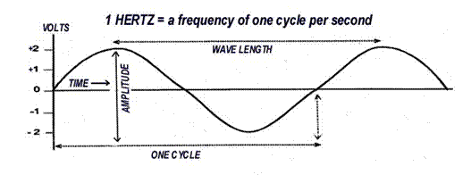
Mains supply AC electricity is the product of an alternator resulting in a pulsing flow generated from their rotating windings within an electromagnetic magnetic field. This AC supply must be converted to extra low voltage DC supply to use in the vessels batteries, starter motor and lighting circuits. In mains supplied battery chargers this voltage reduction is achieved by the use of transformers and rectification (converted from AC to DC) is achieved with diodes (electrical one way valves). Alternators actually generate three pulses of electricity for each revolution of their generating rotors. These phases are more fully described in the next chapter.
Battery charging from
the mains supply
It
is safer to remove a battery from its battery box to the bench if there is risk
of explosive of the hydrogen emitted on charge. Automobiles use the car body as
the negative return. If their positive battery cable touches the car’s body a
spark will occur. Boats use a twin wire system with the metal hull insulated to
limit electrolytic corrosion. Though not essential as with car battery removal,
it is good practice to disconnect the negative battery cable first, secure it
against contacting equipment, and then remove the positive lead and secure.
This limits accidental sparking by touching leads. When reconnecting the
battery to a car, attach the positive lead first and tighten the terminal
clamp, and then the negative cable.
When
connecting the battery to a charger, first remove the cell caps to ensure the electrolyte
covers the cell plates to a height recommended by its manufacturer (usually 4 -
6 mm). Ensure that the positive wire and the negative wire are connected to the
appropriate terminals before switching on the charger. Ensure that the charger
is set on its appropriate 6 volt or 12 volt charge, depending on which battery
you are about to charge.
Most
chargers have a high amperage charge rate and a low amperage charge rate.
Choose the lower rate over a longer period if time permits, or if the higher
rate is selected, then frequently check that the electrolyte is not bubbling
over. When the charger meter or indicator lamps show that the battery is fully
charged, let it sit for 30 minutes as the electrolyte temperature has increased
whilst charging. Cooling is required to take an accurate hydrometer reading.
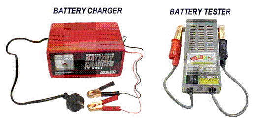
Battery charging from electrical generators
When
a wire coil is moved through a magnetic field, a voltage is induced in that
wire coil. Similarly if a magnetic field was passed over a stationary wire coil
a voltage is induced in that wire coil. This principle enables electricity to
be produced by a motive force
(movement). Devices that produce electricity in this way are all commonly
called generators, but there are several technical types as described below.
The magneto
A magneto is an electrical generator
using wire coils and magnets to produce alternating current. It produces pulses
of high voltage to activate the spark plugs of small petrol driven internal
combustion engines such as light weight outboard motors and lawn mowers.
The shuttle magneto variation spins a wire
coil on its flywheel between the poles of a magnet whereas the inductor
magneto spins the magnet around a static wire coil.
A cam on the drive shaft opens the points (contact breakers) momentary
interrupting the current and collapsing the coil’s electromagnetic field. This induces
a voltage across the coil, which in turn supplies the energy for the spark plug
firing. To prevent high voltage arcing at the point’s contacts, leading to
rapid decay, a capacitor (an
electrical storage and smoothing device) is placed across the points to absorb
the energy burst. (Capacitors, previously
called condensers, are built from two
films of electrical conductors separated by a film of electrical insulator).
The system is rarely used for vehicles or vessels
that have electrical accessories, except for aero piston engines where
simplicity and reliability are of advantage. The magneto is not used to charge
batteries in marine systems but in old outboard motors may be wired to power an
emergency light.
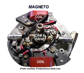
The
dynamo
A dynamo or generator is an electrical generator, belt driven by the motor, using
wire coils and magnets to induce alternating electrical fields which are converted
to direct current at the commutator (a segmented rotary electrical connection/switch using carbon brushes
for continuous contact).
The dynamo has a stationary outer casing providing a magnetic field and a set of windings on an armature (supporting axle assembly) rotating within the field. The
magnetic field is created with either permanent magnets or electromagnets (field coils). Dynamos use their
rotary switch on the armature, the commutator, to output DC current, and an external voltage regulator to control output
over the range of speeds of the driving motor.
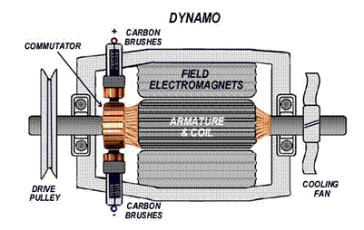
The dynamo operates at any speed with low output at engine idling. The
alternator (described below) cuts in at a minimum speed but has greater output
than the dynamo at idling. Additionally, the complexity and maintenance
requirements of the dynamo’s commutator and brush mechanism have resulted in it
being largely superseded by the alternator for automobile and marine DC battery
charging.
The dynastart
A dynastart
is a combined dynamo/starter motor championed in Stuart Turner’s traditional marine petrol engines, renowned for
their simplicity and reliability. The single unit with fields and coils can
reverse switch its polarity connections to achieve both functions through a
voltage regulator and control box.
The alternator, components and operation
The simple belt driven battery charging alternator consists
of a rotor (a field winding assembly)
rotating within a stator (a
stationary induction winding assembly) so inducing alternating current in the
stator’s three sets of windings.
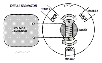
The
batteries require DC for charging so a rectifier bridge (a diode assembly)
converts this to AC while a voltage
regulator (a voltage control device) ensures a steady supply output
throughout the acceleration range of the driving motor. An integral fan or twin
fans (depending on the model type) also provide internal cooling.

Over the iron core of the spinning rotor shaft are
the field windings surrounded by two claw-type finger poles. The ends of the rotor field windings are attached
to twin slip rings that maintain contact during revolution by using brushes and allow current to flow
through to the field windings.
The stator- has three sets
of winding coils evenly spaced around its core, its laminated iron ring
concentrating the magnetic field. Two
differing wirings arrangements are used:
Y - wound stators with three windings with a common neutral connection.
They have three plus one (four) stator lead ends and provide high voltage
output at low rpm. Two windings are in series at any time.
Delta - wound stators with
three stator lead ends provide higher current flow at low rpm. The windings are in parallel.
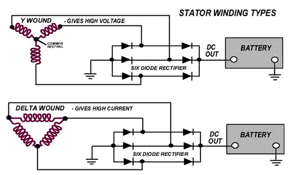
The rectifier bridge - converts the
stator AC output to DC output. Typically six diodes are sat on a heat sink that
dissipates heat. A single diode would block half the output alternating current
(either the positive or negative voltage section of the wave’s cycle) so
efficient rectifiers have both + and - diodes connected to each stator lead. As the rotor
spins the current induced in the stator windings alternate in voltage polarity.
The current paths available at the rectifier enable both the positive and
negative polarity in the wave’s cycle to be fed to the battery as DC output. Full-wave rectification describes this
configuration (shown below).
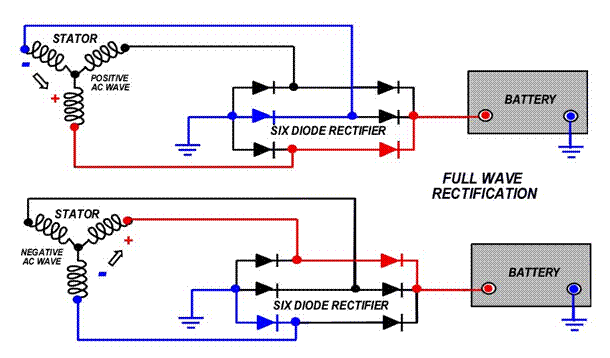
The regulator- The regulator
monitors battery voltage. It maintains a
pre-determined charging system voltage level by increasing or decreasing the
field current (and consequent magnetic field and alternator output) as is
required. The regulator is usually internal but can be external. Two designs are
commonly used:
The grounded
regulator controls the amount of battery ground (negative) going to the
field winding in the rotor.
The grounded
field regulator controls the amount of battery positive (B+) going to the
field winding in the rotor.
Summary of the alternator’s operation - As the alternator’s
rotor spins a magnetic field is generated that saturates the iron finger poles.
One finger pole becomes a north pole and the other a south pole. An alternating
magnetic field from north/south to south/north is
created that induces voltage in the stator so
current begins to flow.
The strength of the magnetic field and the speed of
the rotor affect the amount of voltage induced into the stator. The voltage regulator
monitors battery and stator voltages and will adjust the amount of rotor field
current to control alternator output.
The resultant three overlapping output current waves
from the three sets of winding coils make up the AC stator’s output as three
phase current. The stator output current is led to the diode rectifier bridge
where AC is rectified (converted) to
DC. Six (or eight diodes) are used, half on the positive side and half on the
negative side.

Unlike the auto electrical system where the car
body is itself the negative earth, the marine system is always a twin insulated
wire system. The earth connections shown for simplicity above and in marine DC
systems are fully insulated and connect to the neutral side of the battery. Four
terminals
connect the alternator to the charging system:
IG-
From the ignition switch that turns on the
alternator/regulator assembly.
B- The alternator output terminal that supplies current to
the battery.
S- The battery voltage sensor used by the regulator to
monitor charging at the battery.
L- Used by the regulator to ground the charge warning
lamp.
The F terminal (not shown) is for a regulator full-field bypass.
Twin
battery bank charging alternators
Shown below two separate alternators are wired to
charge the house (deep cycle) and the starter motor batteries (cranking).
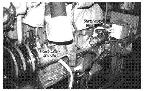
Starting
battery alternator - As
with all alternators, the drive belt tension must be regularly checked to
ensure charging. The alignment is also important to avoid bearing and belt
wear. The battery will absorb a large current until the battery charge level is
approximately 50%. When this is achieved the regulator starts to limit the voltage.
The charge current will level off as the battery voltage level rises.
House battery alternator - A connection diagram below is shown for house and starter alternators with reversed belt drives. Larger and dedicated generator sets (alternators) associated with 240V supply are described in the next chapter.
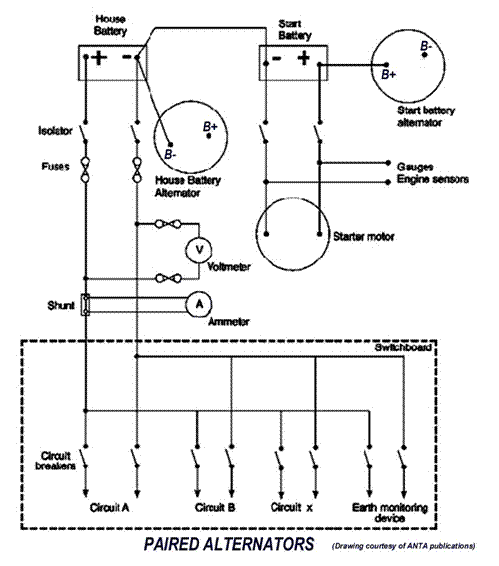
Charging
system failures on a starting battery alternator
Initial output checks are shown by the lamp
as determined by the regulator. Check that
the voltage across the main and negative terminals rises to approximately 14V.
No voltage indicates a total failure of the alternator or regulator. A lower
voltage indicates that some diodes have failed or there is a regulator problem.
It is possible that the brushes in the
alternator are not seated properly on the slip rings. If the voltage is correct,
check the voltage at the battery and ensure that the terminal connections,
leads and isolation diodes are satisfactory. There are two methods of regulator
sensing:
The machine sensing method - monitors
the output voltage and adjusts the alternator output value to approximately 14
volts. It does not allow for voltage drops in the charging circuit caused by
terminal connections, undersized wiring or isolation diodes (if installed).
The battery sensing method - measures
the voltage at the battery and adjusts the alternator output voltage to
compensate for voltage drops in the charging circuit. This ensures the correct
voltage is supplied to the battery. If the warning light does not operate when
the ignition is turned on, check for a lamp or connection fault at the lamp or
the D+ terminal. If
these are satisfactory, the alternator excitation diodes maybe faulty. In
an emergency, if there is a faulty regulator or a partial diode failure, the
regulator can be disconnected and a full field voltage connected to achieve
maximum output.
The
engine starter motor
The starter motor reverses the dynamo’s
principle of using motion within a field to generate electricity by using
electromagnetism to create motion. These motors have very heavy work to do
albeit for a short time so the cabling must be thick, of a short run and have
clean contacts with large surface area to avoid resistance, sparking and
consequent overheating.
|
|
The solenoid forces the pinion outward to temporarily engage with the engines flywheel. On the motors starting and release of the starter switch the pinion springs back clear. Common faults with starter motors are poor connections. The pinion can jam in engagement with the flywheel in older worn starters. If the solenoid indicates that it is working by a click on turning the ignition starting key then a tap on the rear end of the starter motor with a rubber hammer may free it until the required service and repair can be undertaken.
7.4 DC circuit
protection
To protect circuits and users from
electrical accidents a twin wire insulated return is used in marine
applications. The insulation must be in good order and especially checked where
routed through bulkheads (for cuts on sharp edges). Extra low voltage (ELV) marine
systems are completely isolated including engine sensors, starter motors and
alternators.
Preferably there should be a main twin pole isolator (switch to both
positive and neutral wire) to close circuit with the battery bank and fuses to
open circuit in case of overload. Pole switches
are more fully described in the next chapter on AC current. They must be an enclosed
type so sparks or arcs protect from explosion.
An ammeter is installed here to verify safe battery discharge levels. A
volt meter may be installed so that battery charger voltage and charge
condition is monitored.
From
the main switchboard, power is distributed to various switch/fuse combinations
or circuit breakers which either supply circuits to items of equipment or other
distribution boards. An earth indication system is also be fitted in this
switchboard. All circuits should be
protected with a twin pole isolator.
Short circuits
Short
circuits can occur when the positive side of the battery is connected
directly across to the negative side, bypassing the equipment itself. This causes an excessive current flow,
generating heat and causing fire to occur (usually at the smallest wire in the
circuit), unless fuses or circuit breakers are fitted. A dramatic short circuit
will occur if you were to drop a metal tool onto your battery and it were to
touch both battery poles at the same time.
Fuses and circuit breakers
Fuses
are usually fitted to protect DC wiring and equipment from overload. Though
usually reserved for AC wiring, circuit breakers may be found with specific DC applications.
A
fuse - is a thin metal wire designed to open circuit (break) by melting if the
current goes above a certain level, so stopping a surge continuing down the
wiring system. A surge from a short circuit would otherwise cause equipment
damage or electrical fires.
Engine
room fuses must be ceramic or glass encapsulated to avoid being an open
ignition source causing fire or explosion. If a fuse blows, it must be entirely
replaced with the same amperage fuse. A fuse that continuously blows must never
be replaced by a higher amperage fuse that does not, but rather the electrical
problem causing the blow must be identified and repaired.
Circuit
breakers - are load sensitive switches that trip (open circuit) if a predetermined
excess current flows. They are more fully described in the next chapter on AC
current.
Stray
currents are leakage currents which occur when a conductor has an earth fault. They
are often too small to trip circuit breakers or other protection devices.
These
faults are usually caused by moisture in junction boxes or other components,
and from damaged cable insulation. Also,
when operating electric motors for pumps and other equipment, a magnetic field
is produced around and about the motor. This field creates an electrolytic
reaction with the sea water so electrolytic corrosion of the metal hull can
follow.
It
is for this reason that sacrificial anodes are located on the parts of the
vessel most likely to be affected by this reaction. These anodes are made of
materials such as zinc, which corrode before the metal hull or other parts. The
anodes must be replaced regularly. Any faults which may produce stray current
must be rectified as soon as possible.
Because
of the serious effects of stray currents, it is necessary to regularly check
the earth monitoring system as it is imperative that the earth faults be
rectified as soon as practical.
The
cause and cure of electrochemical corrosion is more fully described in Chapter
10, and isolation earthing in the next chapter on AC wiring.
Extra Low Voltage (ELV) systems
Any
system with a voltage below 110 V is known as an Extra Low Voltage (ELV)
system. Systems where the voltage is between 110V and 240V are known as Low
Voltage systems. These are described in the next chapter.
Chapter 8: Marine AC electrical systems
8.1 Electrical safety with AC
Extra Low Voltage Systems (less than 110V) were described in the last chapter. This chapter describes Low Voltage Systems (110V - 440V) and Medium Voltage Systems (over 440V).
DC and AC
Electricity is electron flow along a conductor in the form of DC (direct current) or by AC (alternating current). DC is driven by a steady voltage in one direction only and is the product of the batteries described in the previous chapter.
AC is a pulsing current driven by a voltage wave that alternates between a negative and a positive voltage. The frequency of this cycle is defined in units of Hertz (cycles per
second), and in Australia domestic 240V electricity is supplied at 50 hZ. Beware, other countries such as America (and their ships) may use 60 hZ.
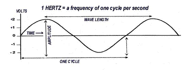
We are more familiar with higher voltage AC systems than higher DC systems. However, take care not to assume the low electrocution risk of 12V systems with higher DC systems. Even moderately higher voltage DC induces a clenched fist reaction that will make an electrocuted victim involuntary grip tight to a cable, whereas at a similar voltage AC may to throw the person off.
AC electricity is produced by an alternator and needs to be converted to DC to use in the vessels batteries, starting and lighting circuits. To do this a diode that only allows electrical flow only in one direction is incorporated in the charging circuit. Alternators also generate three pulses of electricity for each revolution of their generating rotors. These phases are more fully described below in the section three phase.
8.2 Single and three phase
Ship’s Single phase systems are normally 115V AC or 240V AC. These are twin wire systems consisting of one active (positive) conductor and one neutral (negative) conductor. Current standard single phase wire colours in Australia are:
Active -
brown (older
wiring was red)
Neutral
- light blue (older wiring
was black)
Earth
- green and yellow (older wiring was green)
Three phase electricity is generated by an alternator. Three phase supply is much more efficient at transferring electricity over long distances than single phase and uses smaller cabling for the power carried. Due to the triple wave form generated at 120° electrical separation, it also provides a more constant current than single phase that dips through zero volts on every cycle.
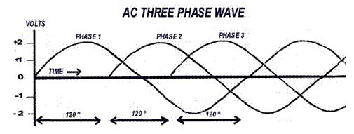
Three phase systems are triple wire systems consisting of three active conductors
and one neutral. Different countries use different colour schemes to identify
each wire. Older Australian colour coding may still be found in aged vessels.
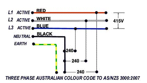
Three phase system enable a number of connection options. It can be used to run three phase equipment, or can be split up as 3 single phase systems using a neutral.
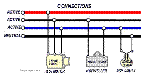
Using three phase without a neutral to obtain 240V single phase is achieved with a transformer.
Transformers
When a wire is moved through a magnetic field, a voltage is induced in that wire, the same thing would happen if the wire was stationary and the magnetic field was moved. This principle enables electricity to be generated.
Also, when a current flows through a wire, a magnetic field is produced around that wire. This principle enables transformers to change one voltage to another.
The transformer has no moving parts except for the magnetic field which is continually changing due to the alternating current. Transformers will not work on direct current (D.C.). They have three main components, the:
Primary coil
Secondary coil
Laminated steel core

The primary and secondary coils are wound on a laminated steel core and insulated from one another. The supply voltage is connected to the primary coil and the load is connected to the secondary coil. The alternating current in the primary coil creates an alternating magnetic flux in the laminated steel core. This flux causes an electromotive force to be induced in the secondary coil.
Transformers can be used to step up or to step down voltages dependant on the ratio of wire turns in each of the opposing coils. (Never disconnect any transformers in the switchboard while the power is on).
Vessels
will normally produce three phase 415V to drive motors.
The reduced voltage from the transformer could be used at 240V to supply
lighting circuits or at 24V to supply a rectifier for recharging batteries or
DC lighting. To achieve this, the control circuit in the main switchboard is
controlled by a step down transformer situated in the switchboard. Also in the
switchboard you would find current
transformers (CT’s) which supply the ammeters
and potential transformers (PTs)
which supply the synchroscope (see
paralleling alternators in next section).
Three phase transformers can be wound on to
one core or they can be three single phase transformers. One advantage of using three single phase
transformers is that if one fails, the remaining two can be connected in an
emergency to still produce three phase at 57% of the initial capacity.
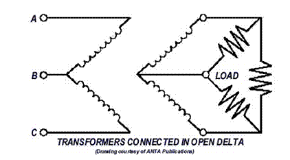
Isolation transformers are used in shore power connection to galvanically
isolate the vessel from its shore power. Eliminating the ground path ashore
reduces electrolytic corrosion. In
isolation transformers the secondary voltage equals the primary voltage.

8.3 AC circuit
protection
Main faults in an electrical system
Extra Low Voltage Systems (less than 110V), Low Voltage Systems (110V - 440V) and Medium Voltage Systems (over 440V) can kill by electrocution if unsafe electrical components and personnel make contact. Low Voltage and Medium Voltage Systems have the potential to arc over in close proximity without actual contact. Consequently it is vital for the Marine Engine Driver to visually check wiring and equipment on a regularly for faults or impending faults. If faults are found they should be referred to a licensed electrician for repairs. Common instances of faults include:
Insulation
on cabling particularly where they pass through bulkheads
Conduits
and glands on motors that have become loose or broken
Loose
wiring connections (become hot and the wires will start to discolour or burn).
Switches
and power points that are cracked or damaged
If any of the above conditions exist, they
must be isolated and rectified as soon as it is practical. The result of a fault
is usually:
Short circuit - a misdirection of the circuit due to
faulty insulation of loose terminal wires.
Open circuit - a break in the
circuit.
Overload - too much current drawn
for the rating of the circuit.
Open circuits can be the result
of short circuit or overload where the wires have blown apart. More difficult to find are intermittent open
circuit faults, such as where a wire has broken hidden inside its covering
insulation sheath - on heating contact is made and on cooling contact is lost.
Electrical circuits must always
be repaired by a licensed electrician. Before commencing work on any faulty
circuit, it must be isolated. A test lamp or a multi-meter will confirm this. Always treat conductors as being live until
you have confirmed otherwise. If for the
safety of the vessel at sea you have to work on a circuit that you have
isolated, always fit danger tags to the isolator so that no other person can
inadvertently switch the isolator on. Never remove a danger tag or switch on an
isolator that was tagged by somebody else.
Always use insulated tools and wear rubber soled insulating shoes. When
working on a switchboard, always remove the shore power lead.
Isolation
In marine applications to protect circuits
and users from electrical accidents a twin wire insulated return is used. The
insulation must be in good order and especially checked where routed through
bulkheads (for cuts on sharp edges). The effectiveness of the rubber or plastic
insulation can be found by inspection for bare wires and by checking the resistance
of the insulation with an electronic circuit tester- a megger tester, so named
as one million ohms of resistance is considered adequate for most 240 volt
systems.
Preferably there should be a main twin pole isolator (switch to both
positive and neutral wire) and fuses or circuit breakers to open the circuit in
case of an overload. Engine room devices
must be an enclosed type so sparks or arcs protect from explosive risks. An ammeter and volt meter can be installed to
verify safe load and supply.
Single and twin pole switches
A two pole switch on AC power supply gives
additional protection as it switches out both the supply power and eliminates
any feedback of power on the neutral side, particularly in the case of reverse
polarity with ship/shore power. A light
switch is usually a single pole switch whereas a main isolator is usually a two
pole switch.

From the main switchboard, power is
distributed to various switch/fuse combinations or circuit breakers which
either supply circuits to items of equipment or other distribution boards. An
earth indication system is also be fitted in this switchboard.
Fuses
and circuit breakers
Fuses may be fitted to protect AC wiring and
equipment from overload, though they are being superseded by the much improved
system of circuit breakers. Short
circuits can occur when the active
cable is inadvertently connected directly across to the neutral side or through
the hull. This can cause an excessive
current flow, generating heat and causing fire (usually centred at the smallest
wire in the circuit) or even cause electrocution to users, unless fuses or
circuit breakers immediately open circuit to cut supply.
A fuse - is
a thin metal wire designed to open
circuit (break) by melting if the current goes above a certain level, so stopping
a surge continuing down the wiring system. A surge from a short circuit would
otherwise cause equipment damage or electrical fires.
Engine room fuses must be ceramic or glass
encapsulated to avoid being an open ignition source that may cause fire or
explosion. If a fuse blows, it must be entirely replaced with the same amperage
fuse. A fuse that continuously blows must never be replaced by a higher
amperage fuse that does not, but rather the electrical problem causing the blow
must be identified and repaired.
A circuit
breaker – is a load sensitive switch that trips (open circuit) if a predetermined excess current flows. Consequently
they activate much more quickly than a fuse so ensuring greater protection for
sensitive electronic equipment and personal protection for higher power
situations. They are easily reset simply by re-switching them to the original
position. They can be used as an additional circuit isolation switch.
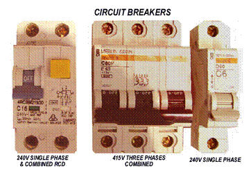
Four types are commonly used.
Thermal
- is
tripped by a bi-metal contact strip that on heating expands differentially to
cause a tripping lever to bend away from the contact with consequent open
circuit. Small overloads with increasing heat build up over a period of time
may trip this system.
Magnetic
- all
or part of the wiring passes through an electromagnetic
coil that at a determined overload setting creates sufficient magnetic
attraction to pull on the tripping lever and break contact. Usually a spring is
incorporated to smooth out current fluctuations. High overloads will trip this
system instantaneously.
Thermal
and magnetic - combining
the two above.
Solid state – immune
to mechanical fault but restricted to smaller load applications.
An additional protective measure (in newer
AC circuitry) is to make the casing of circuit breakers individually sized by
their amperage rating, so a replacement cartridge cannot be mistakenly
installed into an incorrectly rated socket.
Earth faults
A stray electrical current will seek the path of lowest resistance to return to earth and find balance. Consequently safe electrical systems rely on good insulation and devices that provide better paths to earth than through the personnel contacting wiring. This principle is used in the Earth Neutral Systems of land based installations that earth to a metal post driven into the ground. A short circuit causes a high load to escape to earth that trips the circuit protection devices. Ship’s earths are not connected in the same way. Metal hull vessels use a twin wire insulated return. In an insulated neutral distribution system no part of the ship’s active or neutral circuit is connected to ground (earth) - the shipboard system
is completely isolated, including engine sensors and starter motors. Only at the shore side is the shore neutral connected to the shore earth. This has twin benefits:
Prevention from receiving an electric shock
Limiting of electrolytic corrosion
Insulated neutral system - There
is one main earth connection to the hull (vessel ground) which connects to an
earth bus bar in the main switchboard. The earth is then fed to the distribution
boards, outlets, and eventually to all items of equipment. All AC items of
equipment must be earthed. The vessel ground system must never be
interconnected to the DC system negatives. The earthing cable is connected to
the neutral conductor only on the shore side (mains earth neutral system), but no current flows through the ship earth
conductor and as shown below, no current flows though the earth line.
Neutral grounding system - If
a vessel has a genset (alternator) or
inverter then a neutral grounding system is used. In this case the neutral and the
ship’s earth are connected at the genset
only. These wires do not become current carrying as in a short to earth on
shore, and merely bring the neutral voltage back to the earth levels required
to drive electrical loads. Again, neutral to ground flow is only possible at
the shore side earth.
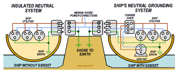
Sometimes a cabling can break down or leak to earth from deterioration of the cable insulation itself or by moisture in junction boxes. These leakages can be very small and will not blow fuses or trip circuit breakers so we must rely on earth monitoring devices to check if conductors are breaking down as are described below.
Earth indication - All AC and DC systems should have some type of earth leakage monitor. This continuous monitoring enables an earth leakage to be immediately detected and rectified quickly. A common monitor used is the leakage test lamp type.
A 3 phase system uses 3 lamps and a test button located on the main switchboard of each system. When the switch is closed, the lamps will be illuminated. If there is a leak on a phase, the lamp on that phase will not be as bright as the others. Sometimes a meter is
installed next to the lamps to indicate the degree of leakage and to activate an alarm at a preset value.
Electrolytic corrosion - The
linking a ship’s underwater earth plate and the shore earth grounding gives
excellent protection against electrocution. However if two ships are floating
in an salt water (an electrolyte)
each with slightly differing earth plates (dissimilar
metals) a battery is formed, a stray current will flow between their earth
plates and galvanic corrosion will occur to one of the vessels. This unfortunate by-product of earthing is
dealt with by galvanic isolation by two primary arrangements:
Galvanic
isolators - A
salt water battery is unlikely to generate more than 1 volt DC. An assembly
totalling four 0.5 volt resist diodes are fitted to a heat sink and connected
across the ships earth cable. A pair of diodes in series each requiring 0.5
volts (1 volt total) to start conducting prevent low (stray) current
transmissions from ship to shore.
Another pair of diodes placed in parallel to them on the same earth
cable, prevent low (stray) current transmissions from shore to ship. At the
same time in the event of higher voltage, as may result from an AC short
circuit, the diodes will allow current passage safely to shore earth.
However, the additional stray AC currents of
over 1 volt often found around busy shore facilities will prompt the diodes to
conduct both AC and DC currents. For this reason a capacitor is incorporated to
block DC current flow.
Isolation
transformer -
The more expensive method of placing a transformer on the vessel between the
shore power lead and the ship connection ensures that there is no physical
cable connection. The current is induced electromagnetically between the two.
The vessels earth system is fully insulated from the shore earth (eliminating a
shore path for galvanic currents) and ship leakage is blocked at the ship side
of the transformer.
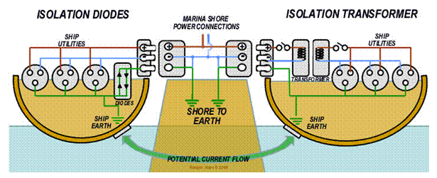
Residual current devices - are
increasingly being used in power supply systems in order to isolate the vessel
from shore power if a shipboard fault occurs. A transformer is used to detect
magnetic fields created by current flow in both the active and neutral wires of
the circuit. Under normal current flow the positive and neutral fields should
balance out so the residual current detected will be zero. If however a short (to
earth) is occurring then one wire will pass more current and create more
magnetic field than the other, so a residual current
will be detected. This generates a tripping signal that activates a relay that
in turn isolates the circuit providing protection. A test function is often
installed.
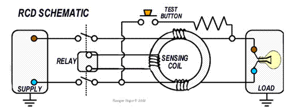
Typically RCDs are set to trip at
30 milliamps within 200 milliseconds as is sufficient to protect human life. It
must be noted that a load such as a light globe that is connected to both
active and neutral simultaneously when its switch is closed will not trip the
device, as the magnetic fields in each wire remain equal. Similarly a person
who holds both wires as a switch is turned on can act as a load and not be
protected. The RCD therefore does not
replace standard overload protection, earths and sound electrical safety
practice.
Earth leakage core balance devices - are particularly useful with extension leads for portable power tools used on shore. In the case of a leak from the active to earth through the operator the function of the earth and active are partially transposed. The result is an imbalance between the active and neutral that is detected by the sensing coil. This in turn activates a relay that trips the isolation switches.
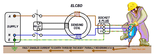
8.4 The genset (engine
driven alternator)
Power Distribution
The power distribution of the ship is controlled from the main switchboard. Warning lights are incorporated to indicate the health and status of the electrical system. Here the ship’s genset/s power and shore power supply can be isolated, monitored and selected through changeover contactors. These operate in the same way as two motor starters in parallel (See 8.4). If ship and shore power were both available it would be necessary to switch off one before switching on the other.
The
changeover contactors are electrically and mechanically interlocked to prevent
both of them being energised simultaneously.

The
load side of the changeover contactors connect directly onto bus bars (common connectors) at the main
switchboard. These bus bars are then
routed through fuses, circuit breakers and/or switches to feed various supply
distribution boards. The sub-circuits from these distribution boards then supply
lighting, power and utility circuits.
There should be wiring schematics pasted inside these distribution board
cabinets to identify each fuse/circuit breaker, its rating and which circuit each
protects.

Precautions should be taken when connecting
to shore power and before closing the breaker on the main switchboard,
including specific checks for:
Voltage
compatibility between shore and vessel (240V to 240V)
Polarity compatibility with your vessel. (Some vessels are wired with a reverse
polarity)
Shore
power supplies run through a fuse, RCD or circuit breaker
Connection
lead is of correct current rating and is faults free (no cuts and abrasions)
Connection
plugs are watertight and free of moisture
Additional
precautions before connecting on a slipway include specific checks that the:
Connecting lead is secured safely and not
lying around the deck area
Vessel shore plug receptacle (CFS) is the same
rating as the one on shore
Vessel earth is not connected to the shore
earth
The
shore power supply may be less than that supplied by the gen set so avoid
overload by switching off unnecessary items of equipment. First ensure that the
3 phases are available. This can be checked by lamps on each phase or by the
volt meter and phase to phase switch. If the 3 phases are not available, do not
connect the vessel to shore power.
If
the phases are okay, the next step is to check the phase rotation via the phase
rotation meter, if the phases are reversed, it will be necessary to correct the
phases using the polarity changeover switch.
Before
bringing the shore power on line, switch off major items of equipment.
Ship/shore
contactor
Switched/fused
shore plug receptacle
The
shore power can now be brought on line. This may entail switching off the ship
power first, if the system is not an automatic changeover type.
The gen set’s driving motor
The
gen set or generator set is usually a diesel motor governed to drive an
alternator at a set speed in order to produce the designed power requirement.
Appropriate pre-departure checks need to be carried out before start up,
including:
|
Step |
Action |
|
1 |
Check
coolant and oil levels. Visually inspect electrical connections. |
|
2 |
Open
the sea cock to allow water sucked up by the pump to cool the system. |
|
3 |
Ensure
the fuel supply is turned on. |
|
4 |
Ensure
the main alternator isolator is switched to off. |
|
5 |
Hold
on the pre-heat switch (glow plug) for around 30 seconds. |
|
6 |
Push
the engine start button. |
|
7 |
Check
that sea water is being discharged or your engine will overheat. |
When the motor has started, check the engine speed, oil pressure and alternator frequency and voltage. The frequency should be 50 Hz, so adjust the engine speed at the governor if required. The gen set’s voltmeter should show 240 volts output. An ammeter should show how much current is being drawn.

Before
closing the main isolator (switching
in the alternator) turn of major items equipment. An overloaded generator will hunt (struggle to maintain speed) and decrease
in RPM. It could trip the circuit breaker or stall even the motor. You can further
reduce the load by shutting down unnecessary lights or utilities. Then close
the main isolator.
Check the frequency and
voltage at the main switchboard and ensure they are registering the correct
readings. If everything is satisfactory, the rest of the load can sequentially be
brought back on line. When shutting the alternator down, it is advisable to
switch major items of plant equipment off first, again to reduce surges at
change over to shore power.
The alternator
The components of a small alternator for battery
charging, being a rotor (a field
winding assembly) rotating within a stator
(a stationary induction winding assembly) that generate AC electricity and
convert to DC has been described in the previous chapter. The genset’s large
alternator uses the same components as its smaller cousin, but the output
utilised is three phase AC (not rectified) that is
used to power the ships heavy equipment or is transformed down to lower voltage
for the ships utilities and general purpose outlets.
Paralleling
Alternators
Alternators are inefficient when running
small loads or if overloaded. If twin or more alternators are installed then another
can be brought on line to meet periods of peak demand. Together they must
produce exactly the same output (line voltage, frequency,
phase sequence, phase angle and waveform) as the operating system - they
must be synchronised. Waveform and
phase sequence are fixed by alternator type and
circuitry at installation. Alternator terminals and
wiring are matched to the systems phase
sequence (order of phase). Connection to the wrong phase sequence would cause
a short circuit.
However voltage, frequency and phase angle must be controlled with each new alternator added. Modern systems are automatic, controlled by Synchronization relays, but manual synchronization is still available with Synchronizing lamps or the Synchroscope.
The following notes are
general only so the users’ manual must be consulted for operating instructions
of your vessel’s specific system. The synchroscope, engine speed governor, and
automatic voltage regulator (AVR) are usually located on the main switchboard. The manual or automatic synchronization process is similar. The genset is
brought up to approximate synchronous speed by progressively increasing
throttle/governor settings. The alternator field is energized and the voltage
at the terminals observed until it meets system voltage and phase angle, when
it is switched into circuit. When synchronized, the frequency varies dependant
on load. Large changes can cause the alternator to drop out of synchronism when
circuit protective devices cut in to disconnect automatically.
Synchronizing
relays - enable automatic and remote operation by the use of sophisticated
microprocessors. A failsafe synchro check
relay is installed that prevents connection beyond a few electrical degrees of
in-phase with the system. Often manual override synchronizing devices are incorporated.
Synchronizing lamps - Three indicator lamps are connected between the alternator’s (instrument transformer) terminals and the system terminals. As the genset’s speed changes, the lights glow bright when the alternator voltage opposes to the system voltage (ahead or behind in-phase). When the alternator voltage matches the system voltage the lights go dim. At that instant, the alternator is switched into circuit and stays in synchronism.
Synchroscope - displays the relative frequencies of system and alternator. The pointer (or indicator lamps) indicate fast
or slow speed of the genset compared to the system requirements. If the pointer rotates (or +/- indicator
lamps show), the engine governor must be adjusted until the needle points
vertically (or top lamp shows) and is steady.
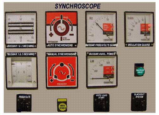
An error of a few
electrical degrees between the alternator and the system on connection will cause a severe drain with abrupt genset
speed change or even stalling. To avoid this isolator is closed as the needle slowly approaches the
in-phase point. Do not leave the synchro switched on as the
synchroscopes are not designed to operate continually.
Alternator
power ratings
The factors in rating an alternator are:
Frequency
and speed
Kilovolt
ampere output in a 3 phase circuit
Number
of phases and terminal voltage
Frequency and speed - frequency varies with the speed and is controlled by the governor. It is calculated by:
Frequency (Hertz) = Speed
x Number of Poles
120
120° is a constant, being 1/3 of the 360° electrical degrees of the three phase wave form. Most alternators are 4 pole machines.
Example - What speed must be achieved to develop a frequency of 50 Hertz using a 4 pole alternator:
Frequency (Hertz) = Speed
x Number of Poles
120
Speed = Frequency x 120 = 50 x 120 = 1500 rpm
Number of Poles 4
Phases and terminal voltage- Australian
vessels commonly use 3 phase 415 volt. Larger motors are designed to run at
these values. Lower voltage rated equipment
of 240V, 115V, 24V use supply stepped down by transformers.
Alternators can be described by their Kilovolt Ampere output. In a 3 phase circuit this is calculated by:
1 kilovolt ampere (KVA) =
√¯3 x Voltage (V)
x Current (I)
1000
Example - How much current could a 20 KVA machine deliver at 415V.
KVA
= √¯3 x
Voltage (V) x Current (I)
1000
I
= 1000 x KVA = 1000
x 20 = 27.82 amps/phase.
√¯3 x V √¯3 x 415
Sometimes alternators are rated in Kilo Watts (KW). A value called the power factor (cosine Ø) is introduced to moderate the previous formula.
kW = √¯3 x
V x I x cos Ø
1000
Simply put, the power factor is the ratio of True Power (kW) to Apparent Power (KVA).
Resistive loads such as incandescent lights and heaters have a power factor of 1.
Inductive loads such as motors and
transformers have a power factor of approx. 0.8.
Sometimes when the alternator is rated in KW, a power factor, usually 0.8, is specified.
The
power factor can be used to calculate unknown values in the formula:
Example - Calculate the current from a 20 kW 415V
alternator with a power factor of 0.8:
kW = √¯3
x V x
I x cos
Ø
1000
I = 1000kW 1000 x 20 =
34.8 amps/phase
√¯3 x
V cos Ø √¯3 x 415 x 0.8
8.5 Motor starter isolation and fuses
Repair or decommissioning of electrical systems
Before repair, decommission or work on electrical equipment, the first priority of the licensed electrical tradesman is to isolate the system for personal safety from electrocution. If no local isolation switch is fitted, he/she must isolate the equipment at the distribution board supply and tag it to protect from inadvertent connection. After isolation he/she will use a test lamp or multi-meter to confirm that the power is actually isolated. If the equipment is to remain isolated or removed from service the relevant fuses and/or circuit breakers will be removed and disconnect from the wiring circuit. Any changes to the wiring plan should be updated in the wiring diagrams.
Motors - If a motor is to be reinstated, checks for loose connections are made. If the connections are tight, then a meter is used to check that the motor resistance between each phase is the same. This is done on the load side of the contactor or the thermal overload and from each phase to earth. If all of these are satisfactory, the motor is manually turned to ensure it is not jammed.
Having completed these checks, the fuse is replaced and power reinstated. Then using a Tong (clamp) type ammeter, the current drawn on each phase is checked to not exceed the current on the motor’s name plate. A thermal overload protects the motor from exceeding the name plate amp rating and a fuse protects the cabling from short circuits. The fuse size can be equalled to the current rating of the cable.
Motors
fuses - If it is necessary to
change a fuse in a motor starter it is first isolated and tagged. Isolating the
starter a test lamp or multi-meter is used for confirmation. Finally the flow fuse is checked for the
correct size.
Motor
starters
Motor starters for electrical motors are used so that the control equipment of start/stop buttons, safety switches and control cabling can be kept to a minimum size. If a 20 KW motor was controlled without a motor starter a 50 amp three phase switch and six 40 amp cables plus similarly rated safety switches would be required. When installing a motor starter only two 1.5 mm cables and single pole 10 amp switches are required.
A motor starter control system
The motor starter stop/start button contactor is a magnetic switch. When power is applied to the coil, the contacts (switches) close and when the power is removed from the coil, the contacts open. There are generally three main contacts that switch the main load and four or more auxiliary contacts used for indication and control. These auxiliary contacts may normally be open or closed, that is, when the coil is de-energised, the contact is either open or closed.

If one of these normally open (NO) auxiliary contacts is connected in parallel with the push button, the contact will close creating a new path for the power to travel to the coil. If the button is released, the coil will still remain energised due to the power flowing through the holding contact. The only way to de-energise the coil is to interrupt the power supply. This can be achieved very easily by installing a stop push button in series with the start push button and the coil. In normal operation, this stop push button is closed but when the stop push button is pressed, the coil is de-energised and the holding contact returns to the normally open position.
Apart from the contactor, the other major element of the motor starter is the thermal overload (TOL). This normally fits directly onto the contactor and has two auxiliary contacts, one normally open (NO) and one normally closed (NC). This device is used to protect the motor from exceeding the main plate amperage, which can occur from various reasons, such as a seized motor or a jammed pumping impeller. The thermal overload will also cut out if the phases are lost due to a blown fuse, if there is a hot or loose electrical connection or a burnt out contact on the contactor. The thermal overload will normally need to be manually reset if it trips on fault.

5.9
Chapter 9: Refrigeration
9.1 Principles of refrigeration
Ship board cooling is required for air conditioning, freezing cargo and for cooling food stores sufficiently to slow the growth of bacteria (between 5° to 8° C) while maintaining a humidity sufficient to prevent its dehydration. Several devices are used including latent heat bush coolers, air cycle, vortex tube, and thermoelectric refrigeration. In remote areas absorption refrigeration and the ice box (esky), are utilised. However, the universal method for ship and shore refrigeration is by using the vapour compression refrigeration cycle.
Terminology
The transfer of heat energy enables refrigeration to occur, so a basic language of refrigeration is used to describe the principles that are involved.
Energy - is measured in units of Joules (J) being the work done in applying a force of one Newton (N) through a distance of one metre (equivalent to lifting an apple one metre). Energy cannot be created or destroyed, but it can change between many forms including kinetic (motive), electrical, light, electromagnetic and heat.
Heat - is measured in units Celsius (C), graded from 0° C when ice melts to 100° C when water boils,
at atmospheric pressure. Heat is a form of energy that is
the result of the molecules in a material being constantly in motion. The
faster molecules move the greater the heat of the material. Only at minus 273.16° C do they stop, this temperature is the
lowest that is possible and therefore called absolute zero. When the
differences in a substances heat are compared for refrigeration calculations
the units Kelvin from the absolute scale of temperature are used, where one
degree K = 1° C + 273.16. The heat interval between a degree Kelvin (1 K) is equivalent to the heat interval between
a degree Celsius (1° C).
Heat
transfer- occurs through convection, radiation or
conduction (see Chapter 3.1 Principles of fire control). Devices constructed to transfer heat are called
a heat exchanger and they play a key
role in refrigeration. A change of heat experienced by a material can either alter
its temperature or, dependant on the pressure it is under, it can change its phase (state) from solid to liquid to
vapour, and vice versa.
When change occurs in
a material’s measured temperature it is termed a sensible heat change.
When heat energy
causes it to change phase it is termed latent
heat change.
When a liquid is frozen
to a solid phase the process releases latent
heat of fusion.
When a vapour
condenses to a liquid phase the process releases latent heat of condensation.
A liquid change to a
vapour phase requires boiling and uses latent
heat of vapourisation.
This can be
experienced by licking your finger and feeling it go cold as the fastest and
hotter moving water molecules vapourise to the wind leaving the slower ones behind.
Pressure
- is measured in kilopascals (kPa), in pounds
per square inch (Psi) or in multiples of one standard atmosphere at sea level (Bars) being equivalent to 101.325 kPa. A vacuum can
exist when the pressure within a space is lower than
that of the atmosphere and it is measured in minus units.
The gauge pressure measured to monitor the
system at the refrigeration servicing points is the pressure exerted by the
refrigerant gas less that of the surrounding atmospheric pressure, i.e. they
are set to read 0 kPa at atmospheric pressure. Absolute pressure is the total pressure experienced by a
refrigerant and includes its own local pressurization within its pipe work
(gauge pressure) added to that of the outside atmospheric pressure. Absolute
pressure is always used in refrigeration calculations where one atmosphere is
taken as 100 kPa. (E.g. with a gauge pressure 220 kPa, absolute pressure = 220
+ 100 = 320 kPa).
Suction or back
pressure refers to the low pressure side of a system, and head or discharge pressure to the high side.
Heat, pressure and
refrigerants – Substances chosen for their ability to change
phase within reasonable pressures and temperatures are selected for use to charge (fill up) a refrigeration system.
Pressure plays a pivotal role in the process of change of phase. The higher the
pressure on a refrigerant, the higher the temperature that is required for it
to boil (vapourise) and vice versa, the lower the pressure the lower the
temperature that is required for it to boil.
Saturation temperature - The energy required to heat a substance
toward boiling point is far less than that required to achieve the boil over. Saturation temperature is the point when
a liquid boils (a saturated liquid)
or vapour condenses (a saturated vapour)
and is dependent on the pressure experienced. Transfer of latent heat into a saturated liquid to boil, or out of a
saturated vapour to condense creates not only phase change but results in high
heat energy transfer.
Subcooled liquid - describes one that is between its freezing
and boiling points and will change temperature with sensible heat without a change
of phase.
Superheated vapour - describes when a vapour is above its
saturation temperature and any change in heat will be sensible as a change in its
temperature.
Principles of refrigeration
Refrigerant gasses
are selected for their ability to readily change phase under reduced pressure,
enabling heat transfer from the freezer using the physical principals of:
Energy cannot be destroyed, only changed
into another form of energy.
(Electricity into heat or heat into movement).
Heat transfers from a material with a high
temperature to one with a lower temperature.
(The
rate of transfer is proportional to the temperature differential).
The boiling point (temperature) of a liquid
rises with the pressure the liquid experiences.
(Water
boils at a lower temperature on a mountain top and higher temperature in a
car’s radiator).
The boiling point of a liquid remains
constant while boiling
(At
boiling point vapour forms, but the unvapourised remnant does not continue to
rise in temperature).
Liquids
absorb considerable heat in boiling (the change from liquid to vapour) and
vapour gives off heat as it reverts
to a liquid.
(The
states of ice, liquid and vapour are termed the phases of a material)
9.2 The vapour compression refrigeration cycle
The refrigeration
system circulates a refrigerant gas through a high pressure section and a low
pressure section. The refrigerant is converted from a vapour phase to a liquid phase,
and heat is transferred as it experiences the four processes of:
Expansion -
Vapourisation - Compression - Condensation
Expansion - High pressured liquid refrigerant that has been collected in the liquid reservoir is sucked towards the refrigeration control device. As it does so, a disposable cartridge or reusable filter drier unit removes any water contaminants that may later damage the compressor pump (water is not compressible). A sight glass enabling refrigerant quality to be monitored is also fitted.
A common refrigeration
control device is the adjustable TX or thermostatic expansion valve.
The expansion of liquid refrigerant reduces
its pressure causing an amount of the liquid to vapourise. Its action
can be likened to the spray nozzle on an aerosol can that allows a controlled
escape of the high pressure liquid refrigerant to a lower pressure region as
mist and vapour. This change of phase
absorbs heat from the freezer cabinet through latent heat of vapourisation.
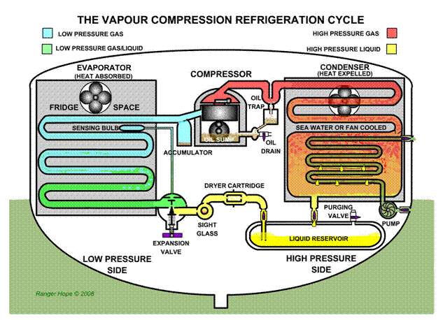
Vaporisation - As liquid refrigerant enters the lower
pressure evaporator from the TX valve a temperature sensing
bulb attached to the outlet of the evaporator sends feedback signals to adjust
the flow rate. As it passes
through the evaporator in the fridge/freezer cabinet the refrigerant absorbs
heat and continues to changes phase as its temperature continues to rise. As
the refrigerant leaves the evaporator it should have entirely changed phase to vapour.
Compression - Before entering the compressor an
accumulator collects any remaining (uncompressible) liquid refrigerants or
water contaminants that would otherwise damage the compressor pump. Knocking
from the compressor termed slugging
indicates liquid contamination. On
entering the compressor the vapourised refrigerant is compressed, raising its
pressure and temperature. The gas is then forced on to the condenser. Any oils
leaked from the compressor are collected in the oil trap where they can be
drained off.
Condensation - For the refrigerant to revert to a liquid phase
it must give up its heat. The condenser allows for this heat to transfer to the
sea (water cooled ship systems) or to the atmosphere (air cooled shore system).
As the refrigerant cools to liquid it is consolidated in the liquid reservoir.
A purging valve is
fitted at this point to remove contaminants that may have built up in the
refrigerant, including air, oil or water and to allow a point to recharge the
system with new refrigerant. A licence is required to handle or service
systems. The refrigerant is directed to recommence the cycle, flowing through
the evaporator and again to the compressor.
The basic components - of the vapour compression refrigeration cycle include:
|
Accumulator |
It prevents
liquid refrigerant from flowing into the compressor to cause knocking and
damage. Liquid reaching the accumulator evaporates. |
|
Cabinet |
Provides cold
storage and houses the cooler tubing and sensor bulb. |
|
Condenser |
It cools the
refrigerant, transferring the heat away, returning it to liquid. Anodes may
be fitted to ship systems. |
|
Compressor |
The compressor
draws the gas refrigerant from the evaporator and forces it to the condenser. |
|
Drier |
Removes moisture
from the liquid refrigerant and prohibit contaminants from blocking the Tx
valve. |
|
Evaporator |
The cooling unit
where heat is absorbed by the refrigerant, evaporating the liquid and turning
it into gas. |
|
Oil trap |
Removes excess
oil from the refrigerant returning it to the compressor. Oils of three types are
used, including polyalkalylene glycol (PAG), polyol ester (POE) or
alkybenzene (AB), each particularly suited to different refrigerants. |
|
Refrigerant |
The liquid used
for heat transfers. |
|
Reservoir |
The container
which holds the liquid refrigerant. |
|
Control valve |
This keeps the
evaporator full of liquid refrigerant while the system is running, allowing
for more efficient cooling. |
Sight gauge – It is installed after the filter dryer and gives
indication of the quality of the refrigerant. Bubbles seen through the sight glass may indicate air or shortage of
refrigerant. Some sight glasses indicate when the system needs recharging. Streaks
seen through the sight glass may indicate oil or water contaminating the
refrigerant. A colour indicator may be fitted that is blue/green when dry and
pink/yellow if moisture is detected.
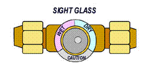
TX Valve - Though not the only type of refrigerant control valve, the adjustable thermostatic expansion valve is commonly used to both maintain a pressure differential between the high and low pressure sections of the system and regulate the flow of refrigerant that can enter the evaporator. A sensing bulb that is positioned at the far end of the evaporator provides a feedback loop to fine tune the flow rate. TX valves are usually set to 10 degrees of superheat to ensure all uncompressible liquid refrigerant is fully vapourised before reaching and potentially damaging the compressor. Flash gas refers to the instant vapourisation of liquid refrigerant.
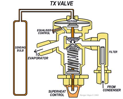
Evaporators - remove heat and so must be at a lower temperature than the freezer cabinet called the evaporator temperature difference. Evaporators can be of the bare pipe type (pipes running through the freezer cabinet) or forced draft coil type (pipes with fins subjected to a blast of air from a fan) that require regular defrosting. Frost back, ice forming on piping, is common in the suction line. The plate surface type of evaporator run through or form brine tanks in fishing vessels that use cold salt water to stow their catch.
Compressor – Several designs of reciprocating compressor
pumps are available. The type shown below uses one way metal flap valves to
hold pressure in a tank above the twin cylinders. The inlet metal flap valve
opens on each piston’s down stroke so gas enters the cylinder. As the piston
rises the inlet valve is forced shut and the compression tank valve above
opens. Compressed gas is forced up. A shut off or bypass arrangement is needed
to avoid over pressurisation of the holding tank and subsequent internal
damage.
The bottom of the
pistons are splash lubricated from an oil sump containing customised oils but a separate oil pump may deliver
lubrication through galleries to all wearing surfaces. An oil level sight gauge
is often fitted. As liquids are non-compressible, measures need to be taken to
avoid water, liquid refrigerant or lubricating oil entering the cylinders to
cause slugging (knocking) or even
more disastrous consequences.
The type below
shows a hermetically (totally) sealed
refrigeration pump but it is not uncommon to find belt driven systems in
fishing vessels where drive arrangements need to be regularly serviced.
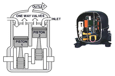
Condensers - give up heat and so must be at a higher temperature than the cooling medium called the condenser temperature difference. Cooling is achieved ashore by fans venting to the atmosphere or usually in vessels by salt water heat exchanger.
Shell and tube, keel coolers or tube within a tube heat exchangers are utilised.
In each case, to maximise heat transfer, the direction of the coolant flow is designed to be opposite that of the refrigerant. The refrigerant gas cools to become liquid in the liquid reservoir, the highest point of which is a convenient access point for purge and re-charge.
Service valves - are fitted at a number of critical points in the system to allow the fitting of gauges to monitor temperature and pressure, and to purge and re-charge.
Use of the manufactures temperature pressure tables (see next section) enables temperature pressure differentials to be calculated.
Safety devices - to assist to monitor and control the plant’s performance and guard
against system failure, damage and leakages include:
|
Electrical
earthing |
Electrical
components must be grounded to prevent electrical shock. |
|
Motor protection |
Fuses/circuit
breakers protect from overloading. Bi-metal switches (temperature opening) provide
protection against overheating. |
|
Pressure gauges |
Used to indicate
the pressure and consequent functionality at various locations within the
system. They are calibrated in KPA and PSI and may incorporate maximum/minimum
temperature record. |
|
Pressure limiters |
Are installed in
systems where the evaporator pressure must not exceed a certain level. |
|
Pressure switches |
Are switches
which react to a set range of pressure changes. They have a cut-out override
control to shut down the system. |
|
Relief valves |
Prevent the build
up of excessive pressures. These valves will generally only function after
all other safety devices have failed. |
|
Service valves |
Access points on
the low and high pressure side of the compressor to install gauges and take
system readings. |
|
Sight glass |
This provides a
visual check for the level of refrigerant in the system and for the presence
of moisture. |
|
Thermometer |
Typically located
inside the evaporator, cabinet, condenser or tubing. |
9.3
Refrigerants
Many substances meet the primary requirement of a refrigerant in that it can readily absorb heat and transfer it to another location and then give up again. In choosing a refrigerant, other factors must be considered including the refrigerant’s stability and cost, the fire, explosive or poisoning risks, the ability to detect leaks, the corrosive effect on plant or equipment and the overall effect on the environment.
Regulations
and control
Some chlorine rich fluorocarbon refrigerants
such as chlorofluorocarbons (CFCs)
and hydrochlorofluorocarbons (HCFCs)
cause severe environmental damage by depleting the earth’s protective ozone
layer. At the Montreal Convention in 1987, international action initiated banning
or phasing out the worst of these substances. Bromofluorocarbons (Halon) and hydrobromofluorocarbons
(HBFCs) are now banned and signatory countries control use by restrictions
on sales and operating requirements (licensing) for repairers.
The Commonwealth is a party to the
international agreements to further controls. Since 1996 CFCs have been banned and
HCFCs have been classified as controlled substances requiring special licences.
A total ban of HCFCs is scheduled by 2020. The control is devolved to State and
Territory governments whose enforcement agencies include their Environmental
Protection Agencies, Workcover and Maritime Authorities.
Industry associations and manufacturers are
sources for product information regarding usage restrictions and handling in
product hazardous material data safety
sheets. Some existing refrigeration plants will not be economic to adapt to
the use of a newer compliant refrigerants. Awareness of the currently banned or
restricted use refrigerants is critical in order to monitor compliance of the
system on your vessel. While the refrigerants are carefully controlled so are
repairers and refrigerant sales- both activities require licensing.
Refrigerants safety
When dealing with
refrigerants special care must be taken to avoid both personal injury and
environmental damage when filling or purging the system, or if a leak occurs.
Detectors are available for refrigeration system leakage,
the most common called a halide leak detector.
PPEs are advised
while working on systems. All refrigerants on contact with the skin will cause
a freeze burn. Due to its pressurisation, the possibility of squirts into the
eyes with leaks is a high possibility. In the event of an accident immediate
first aid will include irrigation and seeking medical assistance. Fluorocarbon refrigerants
are heavier than air and can lead to asphyxiation and death in confined spaces.
In affected persons fresh air and resuscitation will be required immediately.
Refrigerant storage
cylinders should be stowed with their thread caps fitted to prevent damage,
kept away from the sun or heat and never be more than ¾ full. Refrigerant
storage cylinders are colour coded to Australian Standards for initial
identification. The correct refrigerant and coloured cylinder must always be used appropriately.
However, be wary that this precaution has carelessly not been observed.
To positively
identify the refrigerant, a compound gauge can be fitted to measure the
cylinder pressure and the temperature at the bottom of the cylinder. Using a pressure temperature chart the refrigerant
can be identified.
Types of refrigerants
Different
refrigerants are used dependant on the refrigeration system and its purpose. They
are grouped under three main types:
Group One: Safest of the refrigerants
Group Two: Toxic and some flammable refrigerants
Group Three: Flammable refrigerants
Despite some of
these refrigerants being called non-toxic, care must be taken when handling the
material to avoid any possibility personal injury. By itself a refrigerant may
be relatively harmless, but having been introduced to the air, flame or hot
metal, the refrigerant may break down into dangerous by-products such as acid
or gas.
Listed below are
common refrigerants, their characteristics and associated hazards:
Group One
R12 Dichlorodifluoromethane -is a popular
liquid refrigerant which is colourless and almost odourless. It is not toxic,
does not irritate, does not corrode and is non-flammable. Found in air
conditioning (especially in vehicles) and refrigeration systems.
R22 Monochlorodifluoromethane - is a
synthetic refrigerant and is used in refrigeration systems which a low
evaporating temperature. It is not toxic, does not irritate, does not corrode
and is non-flammable. Used in air conditioners and domestic and commercial
refrigeration systems.
R134a Tetrafluoroethane - is the common
replacement for many R12 applications where a medium evaporating temperature is
required.
R502 Azeotropic mixture - This is a liquid
mixture of refrigerants and is non-flammable, non-corrosive and is generally
not toxic. R502 is used in systems requiring low to medium evaporating
temperatures. Generally used in commercial refrigeration systems.
Group Two
R717 Ammonia - is common in industrial
applications and is a chemical compound. It is flammable and can form an
explosive mixture with air. In small quantities R717 is not poisonous but will
severely irritate the respiratory system. Large exposure must be avoided. The
gas has a strong and ugly odour and is easily detected. Exposure can cause
burns, eye injury and loss of consciousness. Protective clothing and breathing
apparatus should be worn when dealing with this refrigerant.
Group Three
Include R170 Ethane, R290 Propane,
R600 Butane, R601 Isobutane and R1150 Ethylene.
All
are highly flammable.
Temperature
pressure tables
These tables are available from your refrigerant gas supplier and they show the pressure that a refrigerant requires to change phase - it indicates the saturation temperature of a number of common refrigerants at a given pressure and consequently can also be used to identify the type of refrigerant.
To determine the
pressure for R22 to vapourise at -12°C, scan across from the tabulated
temperature to the pressure
reading of 229 kPa. To find the gauge pressure required from the absolute
pressures tabulated, one atmosphere has to be subtracted:
229
kPa (absolute pressure) -100
kPa (atmospheric pressure) = 119 kPa (gauge pressure)
|
Refrigerant
Pressure Temperature Chart For example and study use only courtesy of Reece plumbing supplies
http://www.reece.com.au |
||||||||
|
°C |
R22 |
R134a |
R507 |
R410A |
R404A |
R404A |
R407C |
R407C |
|
Saturated Conditions |
Bubble |
Dew |
Bubble |
Dew |
||||
|
kPa |
kPa |
kPa |
kPa |
kPa |
kPa |
kPa |
kPa |
|
|
-40 |
-50 |
37 |
73 |
34 |
30 |
19 |
-16 |
|
|
-38 |
14 |
-45 |
50 |
90 |
47 |
42 |
30 |
-7 |
|
-36 |
25 |
-38 |
64 |
108 |
60 |
55 |
43 |
3 |
|
-34 |
37 |
-32 |
79 |
126 |
75 |
69 |
56 |
14 |
|
-32 |
49 |
-25 |
95 |
147 |
90 |
85 |
71 |
25 |
|
-30 |
63 |
-17 |
111 |
168 |
106 |
101 |
86 |
37 |
|
-28 |
77 |
-9 |
129 |
191 |
124 |
118 |
102 |
51 |
|
-26 |
92 |
0 |
148 |
215 |
143 |
137 |
119 |
65 |
|
-24 |
108 |
10 |
169 |
241 |
162 |
156 |
138 |
80 |
|
-22 |
126 |
20 |
190 |
269 |
183 |
177 |
158 |
96 |
|
-20 |
144 |
31 |
213 |
298 |
206 |
199 |
179 |
113 |
|
-18 |
163 |
43 |
237 |
329 |
229 |
222 |
201 |
132 |
|
-16 |
184 |
56 |
263 |
362 |
254 |
247 |
224 |
152 |
|
-14 |
206 |
69 |
290 |
396 |
281 |
273 |
249 |
172 |
|
-12 |
229 |
84 |
318 |
433 |
308 |
300 |
276 |
195 |
|
-10 |
253 |
99 |
348 |
471 |
338 |
329 |
303 |
218 |
|
-8 |
279 |
116 |
379 |
512 |
369 |
360 |
333 |
244 |
|
-6 |
306 |
133 |
413 |
555 |
401 |
392 |
364 |
270 |
|
-4 |
335 |
151 |
448 |
600 |
435 |
426 |
396 |
298 |
|
-2 |
365 |
171 |
484 |
647 |
471 |
462 |
430 |
328 |
|
0 |
397 |
191 |
523 |
697 |
509 |
499 |
467 |
359 |
|
2 |
430 |
213 |
563 |
749 |
548 |
538 |
504 |
392 |
|
4 |
465 |
236 |
605 |
804 |
590 |
579 |
544 |
427 |
|
6 |
501 |
261 |
649 |
861 |
633 |
622 |
586 |
464 |
|
8 |
540 |
286 |
696 |
921 |
678 |
667 |
629 |
503 |
|
10 |
580 |
313 |
744 |
983 |
726 |
714 |
675 |
544 |
|
12 |
621 |
342 |
794 |
1049 |
775 |
764 |
723 |
586 |
|
14 |
665 |
372 |
847 |
1118 |
827 |
815 |
773 |
631 |
|
16 |
711 |
403 |
902 |
1189 |
881 |
869 |
825 |
678 |
|
18 |
759 |
436 |
960 |
1264 |
937 |
925 |
879 |
727 |
|
20 |
809 |
470 |
1020 |
1342 |
996 |
983 |
936 |
779 |
|
22 |
861 |
507 |
1082 |
1423 |
1057 |
1044 |
995 |
833 |
|
24 |
915 |
544 |
1147 |
1507 |
1120 |
1107 |
1057 |
889 |
|
26 |
971 |
584 |
1214 |
1595 |
1187 |
1173 |
1121 |
949 |
|
28 |
1030 |
626 |
1284 |
1687 |
1255 |
1242 |
1188 |
1010 |
|
30 |
1091 |
669 |
1357 |
1782 |
1327 |
1313 |
1258 |
1075 |
|
32 |
1154 |
714 |
1433 |
1881 |
1401 |
1387 |
1330 |
1142 |
|
34 |
1220 |
761 |
1512 |
1984 |
1479 |
1464 |
1405 |
1212 |
|
36 |
1288 |
810 |
1594 |
2091 |
1559 |
1544 |
1483 |
1285 |
|
38 |
1359 |
862 |
1679 |
2202 |
1642 |
1627 |
1564 |
1361 |
|
40 |
1432 |
915 |
1767 |
2317 |
1728 |
1713 |
1648 |
1440 |
9.4 Common faults
Modern refrigeration systems are highly
reliable, so user servicing should primarily be that advised in the
manufacturer’s operating manual. Maintenance will probably be limited to
topping compressor oil levels, changing filter dryers, monitoring
temperature pressure differentials in order to tweak superheat control and
freezer cabinet temperature, the occasional defrosting and servicing of salt
water cooling strainers and anodes. Any work planned beyond this must take
account of the legislated requirement of a licensed operator to undertake any
works where refrigerant leakage is conceivable. However, the following table summarises
some of the more common problems.
|
Compressor motor faults |
Possible cause |
|
Will not start |
Isolation switch is open. Circuit breakers are tripped. No immediate demand for the compressor. Anti recycle timer operating- wait until
time out auto completes. Loose electrical contacts. Low oil pressure safety cut out. High refrigerant pressure safety cut out. Motor seized. Motor windings shorting or burnt out. |
|
Hums but will not start |
Over tight drive belts. Mechanical failure,
bearing or frictional overload. Low voltage supply to motor. Operating on one phase due to broken
connection. |
|
Shuts down after start/short cycles |
See pressure faults. |
|
Motor runs continually |
Too lower temperature set for conditions. Condenser cooler blocked. |
|
Motor runs hot and is noisy |
Low lube oil or worn compressor bearings.
Overload. |
|
Pressure Faults |
Possible cause |
|
Low pressure |
Low refrigerant level. Check for leakages. There may be a blockage in the tubing. The could
be a leak in the compressor. There is ice build up on the evaporator. There may be a blockage in the drier core. Moisture may have frozen in the
thermostatic expansion valve. |
|
High pressure |
There is too much refrigerant
in the system. There could be air in the system. There may be a blockage in the condenser
unit. |
|
Moisture |
Could have entered the system on
installation or on replacement of parts. Can result from leaks. |
Chapter 10: Slipping, inspection and repair
10.1 Forces and
stress
Terminology
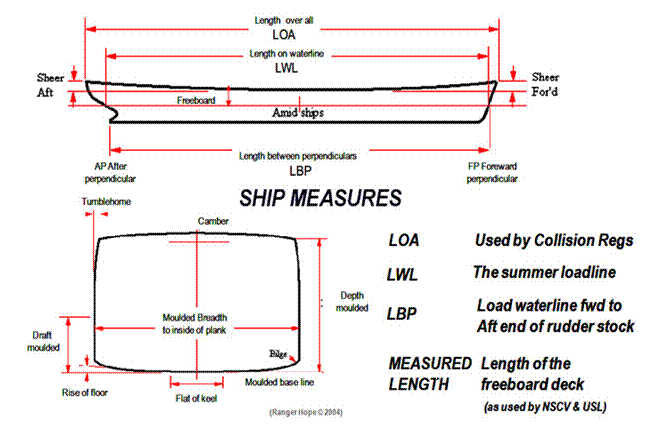
The bow is the front and the stern is
the back of a vessel. To move towards the bow is to go forward and move towards
the stern is to go aft. To move along the length of a vessel is to go in
a longitudinal direction. To move across a vessel is to go in a transverse
direction. When facing forward, the left hand of a vessel is the port side
and the right hand is the starboard side.
Amidships - is
the vessel’s mid length and defines the point at the centre of the LBP.
Freeboard - the
distance from deck to waterline.
Sheer – is
the vessel’s the deck line curves forward and aft. It aids water runoff and
contributes to reserve buoyancy.
Length Overall (LOA) - the
length from the extreme tip of the bow to the aftermost point of the stern. This
length used in the International
Regulations for Preventing Collision at Sea.
Load on the waterline (LOL) - is
dependent on the placement of cargo and stores (the loading condition). A vessel at the planned fully loaded
condition is said to be floating at its design waterline.
Length between perpendiculars (LBP) – is a
distance between two vertical lines at each end of a ship’s profile plan that
ship designers’ use to space out regular sections (stations or frames). It is usually
taken as a vertical line drawn through the point where the load waterline cuts
the stem (the forward perpendicular) and a vertical line drawn at the after end
of the rudder post (after perpendicular).
Measured length - is
the distance from the front of the hull to the back of the hull, taken at the
upper side of the uppermost watertight deck, or in open vessels, at the height
of the gunwale. Specific vessel variations are found in Part B NSCV.
Moulded depth - is
the internal distance from deck to keel plates or timbers.
Moulded breadth - is
measured at the widest part of the vessel. It is the greatest width internally from
one side of the vessel to the other.
Beam - is
measured at the widest part of the vessel. It is the greatest width externally from
one side of the vessel to the other.
Draught - is
measured from the waterline to the bottom of the vessel. When the vessel is
fully loaded it is termed the loaded draught or the service draught.
Some vessels have a keel parallel to the design waterline while others one
angled to it. In the latter case the angle is described as the declivity of
keel.
Flat of bottom - is the
area of the hull near the keel that in some vessels is flat.
Bilge - is the
rounded hull where the side meets the bottom to provide strength and reduce
hull stresses.
Rise of floor (deadrise) - is the area of the hull near
the keel that in some vessels rises from the centre line to the turn of bilge.
Camber - is
where the deck of a vessel has an upward curve to help water to run off and
reduce deck stresses.
Tumblehome - describes
where in some vessels the uppermost sides plates curve inwards to provide
intrinsic strength and greater buoyancy on initial heeling.
Flare - is the
concave curving of the bow faces that drives water away from the vessel,
promoting deck dryness but reducing intrinsic bow strength.
Bluff bowed - is the
convex curving of the bow faces that forces water outwards, increasing intrinsic
strength. They can be wet boats (take
spray over the bow).
Rake - is any
structure that is bent from the vertical, including bow, stern, mast , funnel etc.
Force
and stress
Force
can be experienced by a material as:
Compression - squeezing, such as experienced by a post supporting a weight.
Tension - the stretching of a material such as experienced by a cable
lifting a weight.
Sheer - the
tearing apart of a material such as experienced by ripping.
Torsion
- the twisting action such as between
a rotating engine and its support bolts.
Flex
- the bending of a material such as
experienced by a mast in the wind.
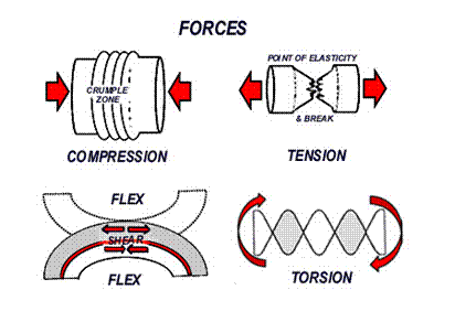
The
evidence of over compression is
indicated by buckling and over tension
by stretching and thinning until a point of ultimate elasticity is reached and
failure occurs (a break). In a flexing
material the upper and lower sides alternate between compression and tension.
The central zone between is experiencing shear.
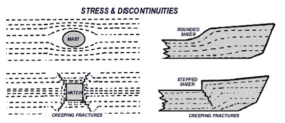
Stress
is a force experienced over a determined surface area. If the force is
concentrated over a small area, such as a heavy deck mounted piece of
machinery, it is said to experience a point
load or point stress. Often a
force is spread over a wider area that be visualised as a radiating web of
stress lines. Rounded shapes are capable of evenly distributing the stress,
whereas (poorly designed) square edged structures create points of stress
concentration. The weakness in the affected area from these discontinuities are more likely to
be the starting point of creeping cracks or even structural fracture.
A
vessel encounters particular stress from both sea conditions and its trading, including:
Static forces of water pressure
resulting from immersion
Stress from unbalanced weight and
buoyancy
Stress from the dynamic action of
wind and waves
Stress from point loading such as
cargo and machinery
Stresses from dry dock and slipping
Forces
from static water pressure
Water
pressure acts at 90° to the
underwater hull surface. To counteract this constant pressure the hull is
reinforced both longitudinally and transversely.

Stress
from unbalanced weight and buoyancy
Uneven
loading can cause flex over the length of keel but is more dramatically
experienced as shear between compartments, as described below.
Shear - occurs when the vessel’s spaces are unevenly loaded, and buoyancy and weight act in opposition along an adjoining surface (bulkhead). Adequately engineered bulkheads and planned loading are required.

Stress
from dynamic wave action
Wave
action dynamically acts at 90° to the
underwater hull surface. To counteract this constant pressure the hull is
reinforced both longitudinally and transversely.
Hogging - Is the longitudinal bending of the hull caused by a wave supporting the vessel on crest amidships or due to poor longitudinal weight distribution of the vessel.
Sagging - Is the longitudinal bending of the hull caused by a wave supporting the vessel at bow and stern only or due to poor longitudinal weight distribution of the vessel.

Alternation between hogging and sagging creates flex along the keel. Large steel tankers travelling between tropical and winter zones may experience differential heating between deck and underwater zones sufficient to hog or sag the vessel and alter the apparent position of the amidships summer load line. Care must also be taken when slipping to adequately support the full keel length to avoid permanent deformation. Longitudinal constructional fortitude of the keel, hog, side plate and deck resist hog and sag.
Pitching - is the action of the vessel being longitudinally lifted by a wave and then dropped into the next trough. This stresses both the stem and the stern structures which are reinforced accordingly.
Pounding - is heavy pitching assisted by heaving as the whole vessel is lifted out of the water and slammed on top of the next wave, causing stress to the stem and forefoot. Similarly, with an overhanging counter type stern, its underside being hit on re-entering the water is termed slapping. Doubling of floors and plate is utilised to reinforce structure.

Panting – is the result of water pressure variations on the end hull plating of the vessel when pitching heavily in a seaway. If uncontrolled the waves may actually deflect the hull plate, especially if the vessel continues to make headway, resulting in plate flex and a possible pumping action that can suck sea water into the vessel.

Racking - occurs to the body of the vessel rolling in a seaway due to water pressure variations on the hull plating. The waves act to deflect the hull out of the square. Brackets and knees are used to counteract this force.

Stress
from point loading such as cargo and machinery
Under
any winches, windlasses, hawse pipes and masts the supporting deck experiences point
loads are that are typically resisted by doubling the thickness of the deck
plating and/or by supportive underdeck posts or pillars. The bow and forefoot
must bear the first impact of a collision and the stern area must resist the
continuous stresses of torsion around the propeller shaft, rudder post and
engine bearers.

Stress
caused by dry dock and slipping
The vessel is built to withstand the forces of water pressure pushing inward. In water the weight of the vessel is balanced by the external water pressure. When removed from the water to the slip these forces are removed so it must be well supported by toms or chocks.
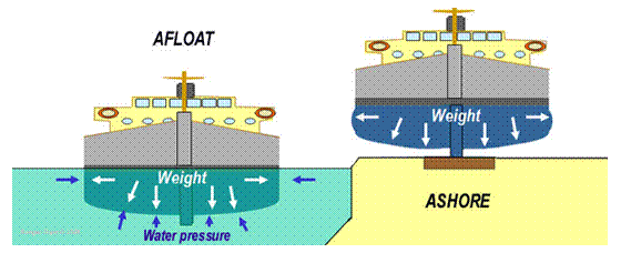
Poor support on the slip can result in permanent hog or sag particularly with elderly timber vessels where the continuous working of fastenings to widen their driven holes and/or the corrosion of fastenings themselves has created the terminal condition called nail sickness.

Particular
care needs to be taken if vessels have extreme overhangs as much of the weight
must be supported over a concentrated area, a point load, such as with fin
keeled yachts. As shown below are the tell tale fractures at discontinuities in a fin keeled hull that
has been badly propped or has grounded, and the method to shore and prop correctly.
10.2 Structures
of a vessel
Vessels are constructed as a floating platform (hull) with enclosed areas for stowage and machinery (holds and spaces). Open work areas (decks) and accommodation (super structure) are built over the hull.
The
hull
A variety of hull materials can be used, each with structural properties that are described in the next section. The hull may be of monocoque construction, having a continuous watertight skin as with fibreglass vessels, or be built from component parts, as with a planked timber vessels. Some vessels are built from components and then fused into a monocoque structure such as welded steel vessels. Monocoque construction creates a rigid hull while component vessels have give (flexibility), but also the inherent weakness of seams that will leak if the joint sealant fails.
Hull designs include flat bottomed, (the simplest), round bottomed or chine construction. Chined uses two flat planes of material such steel or plywood sheets bonded create the vessel’s body. If the angle at the bow is sharp it is called hard chined or a v bottom construction, noted for an ability to drive through waves. If multiple sheets are used, this build resembling the continuous curve of a round bottom construction is called multi-chine.
Whatever method used, the hull must resist the
longitudinal and transverse stresses of hogging, sagging and racking. Component
construction solutions include additional, doubling or thickening of strengthening
members and monocoque solutions include local thickening of hull and
intelligent use of design shape to optimise stress resistance.
Timber construction - longitudinal
strengthening
Being the earliest of constructional materials used, the solutions found and names given have evolved as almost another language to the landsman. Some structures have several alternatives names or are even named entirely differently dependant on locality or material of construction. However the underlying principles to resist stress remain the same.
The keel is joined to the stem by a scarfed joint and at the stern by a mortise and tenon joint. A dowel pulls the tenon tight into the mortise and a fish plate (a shaped and rebated joining plate) keeps it there. Brackets reinforce the back of the keel to stem and stern joins. The strongest type is shaped from the natural curve of a compass timber (a tree’s bough) and is termed a grown chock. One that is sawn diagonally from a standard plank to follow the grain is called a sawn chock. Another method is to sandwich several boards together, shape them and then drift bolt them together. This type of bracket has little intrinsic strength and relies on its fastenings; hence it is named a deadwood.
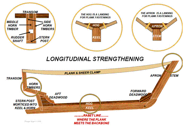
Where the side planks meet the backbone the keel, stem and stern post have to be longitudinally rebated (the rabet) to accept the plank edge’s changing angle of incidence. At amidships the edge of the plank is nearly parallel to the side of the keel, but at the bow and stern it lands at an acute angle. That angle of incidence would make it difficult to skew in a plank fastening to attach to the backbone without the common solution of fitting a hog and apron to provide the landing (point of attachment) for fastenings.
Stem is the
extreme forward member of the backbone of a vessel and has to be very strong to
resist pitching and pounding stress as well as that from potential collision.
The strongest type of bracket to reinforce the bow scarf is the grown chock shown below. Good practice is to drill a transverse hole through the scarf and drive through a waterway (dowel) that swells and seals the scarf’s join from seeping all the way into the hog.
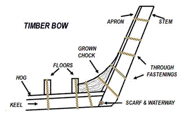
Panting stress is addressed in larger timber
vessels by spacing the frames so close that they are fitted literally side by
side. The upward extension of the foremost group of these frames is called the knights head and this supports the bow
sprit.
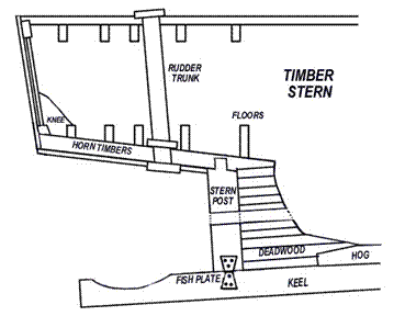
Stern Post is mortised
into the keel below and sandwiched between the twin horn timbers above. A fish
plate secures its bottom end. Stern deadwood is massive to allow for the stern
tube tunnel to be drilled for the propeller shaft.
Timber construction - transverse
strengthening
The compressive forces from water pressure are resisted by thwarts (seats) and ribs in small craft and deck beams and sawn frames and/or bulkheads in larger vessels. In the round bottom construction shown below, this small vessel’s ribs may be laminated and glued or bent by applying steam (steam bent) when they are called timbers.
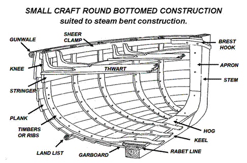
In the chine
construction sawn frames are more
common and webs (built
up frames) provide additional rigidity. The labour intensive steam bending process is
only required at the forward plank ends. The bottom short cross-plank
makes for economic use
of short boards of timber. The
transverse section is built from floors
and brackets (knees). Limber holes drilled through the floors allow
bilge water to flow to the lowest point and bilge pump.
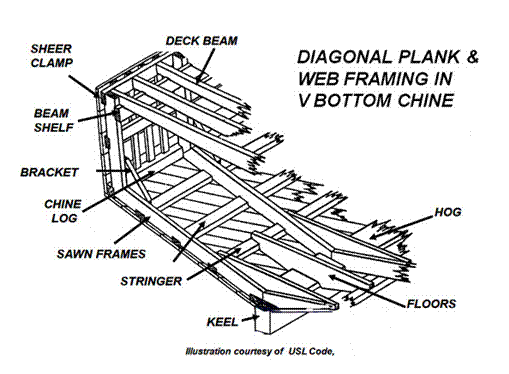
In this construction the deck beams are supported
by the longitudinal beam shelf, and
the frame tops tied together by the longitudinal sheer clamp. This poorly ventilated area can be prone to rot
especially at the vessel’s ends and where excessive tumblehome occurs.
Timber construction – planking - The
deck, rails, sheer clamp, and side planks also contribute to
longitudinal strengthening. The lowest and first side plank fitted beside the
keel is called the garboard. Differing planking methods are used.
The lightest and most
flexible method is the traditional clinker build. The carvel system
requires the plank seams (gaps) to be packed with cotton fibres
or oakum (hemp fibres) to keep them watertight. This is called caulking.
Oakum should always be used under engine rooms as the diesel and oil weeps rots
cotton quickly. In tropical Australia open boats that are left out under the
hot sun are often partial double skinned by backing over the seams of their
carvel construction with thin stringers. Though if properly executed the clenched
nail (worked into a U shape by counter hammering) is strong, the copper
nail and rove (worked rivet) is a superior method allowing tightening with
progressive ageing.
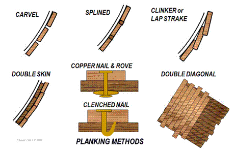
The modern technology of
superior waterproof epoxy glues, resins and varnishes has been harnessed in a
variation of the double diagonal system called cold moulding. Cold
moulded vessels are built with layers of thin laminations separated by
waterproof membranes. They can be round bottomed with all the superior strength
and light weight achieved by plywood but are monocoque with the great advantage
of no seams to pack to prevent leaking. However, repairs to impact damage are
problematic.

Steel construction - longitudinal
strengthening
Principles
of steel construction mimic those of timber but with some significant changes
in terminology. Steel construction calls major longitudinal members girders, minor ones longitudinals, and major transverse members are called floors and beams.
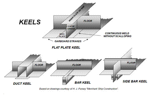
Steel
construction utilised various types of centrally placed keel to resist
bending of the hull in a longitudinal direction. A small vessel may use a bar keel but flat plate keels are standard construction. A longitudinal centre girder runs along the ship’s
centre line fitted at right angles to the flat plate keel. If a side girders or side keelson is fitted parallel to the central girder it may be constructed of
many short plates individually slipped in between the floors. A rider bar is welded over the top to join the component
plates. The whole then welded together is called an intercostals side keelson. Larger vessels may use a duct keel that
forms an internal watertight passage used for carrying the vessel’s pipes and
shafting.
Steel construction - transverse
strengthening
The bottom shell plating is stiffened by means of
transverse members called floors.

The floors support the base of the frames at the
zone where the hull shell plates change from side plates to bottom plates at
the turn of the bilge. This area may
be supported against racking by additional
brackets.
Steel construction - watertight subdivision
- The
greatest transverse strength is provided by bulkheads
(solid walls between a vessel’s compartments). Bulkheads have great resistance
to racking,
provide watertight zones (that limit flooding) and fire check zones (that limit
fire spread). The number, position and construction of bulkheads according to the
vessel’s measured length is specified in USL, NSCV or Classification Society
Rules (see Chapter One)
USL vessels of 12.5 metres and over in measured
length must have a watertight bulkhead at each end of the engine room (except
where it is located at the extreme end of the vessel). The bulkhead at the back
of the engine room is called the aft peak
bulkhead. Vessels of 16 metres or over measured length must have a dedicated
watertight bulkhead called a collision bulkhead fitted
at the bow. An intervening space between two bulkheads is called a cofferdam
when it is used to stop contamination seepage between close tanks such as oil
tank and a fresh water tank. Alternatively a cofferdam can be filled
with water to improve fire control between two fuel oil tanks.
Steel construction - double bottom - construction
is used on larger vessels to act as tank space for fuel, ballast and fresh
water. Additionally it provides an extra safety, since in the event of bottom plate
holing only the double bottom tank is flooded. The girders and floors are
perforated with holes called lightening
holes both to reduce weight and to provide access to and between the double
bottom tanks. The turn of the bilge is reinforced at the margin with a
composite longitudinal margin plate
with braces (brackets). The tanks are plated over with a steel top with
strategically placed entry manholes. At the margin a gusset is used to reinforce the top of the margin tanks. The tank
top can be lined with a ceiling (timber
deck planking).
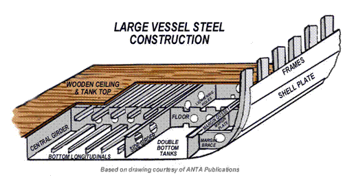
The
condition of the tanks is critical so the tank tops and valves into the tanks
must be routinely inspected for deterioration. A small undetected leak from the
bottom plate will initially struggle to enter the vessel against the pressure
of the tank, but if a corroded tank top is traumatically breached the leak may
become a torrent. It is common for vessels to be detained by harbour authorities
due to tank top and/or valve corrosion issues.
The
internal tank surfaces of large vessels are traditionally coated with concrete
screed to reduce corrosion. Modern mastic based materials are available. If it is necessary to enter such a confined space,
make sure that it is absolutely safe to do so. Ensure occupational health and
safety requirements have been addressed including isolating services into the
tank, venting, testing and issue of gas free and permit work certificates, posting
a sentry and providing rescue apparatus.
Steel construction - aft and forward ends
- The aft
end of a vessel experiences torsion stresses from both the propeller shaft and
rudder stock. Any overhanging structure can experience severe slamming forces
in heavy weather so the structure is suitably stiffened by doubling the floors
and providing brackets. The shell plating terminates at a massive stern frame
structure which in single screw vessels has a tunnel for the propeller shaft. Multi
screw vessel’s stern frames can be much smaller and use A or P shaped brackets to
hang the propeller shafts outer bearing clear of the hull’s bottom and similarly
protruding skegs for the twin semi-balanced rudders.
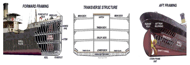
The stem (forward
most part of the vessel’s hull) is constructed of a stem bar from keel to water
line and a stiffened plate structure up to the forecastle deck. The side shell
plating may be flared outward to increase the deck area and to deflect spray
away from the ship. Some vessels are fitted with a bulbous bow (a protrusion below the waterline) designed to increase
the vessel’s speed by throwing water away from the remainder of the square hull.
Steel construction - panting and pounding - Stiffening
structures are provided to strengthen the bow. To resist pounding the frame spacing is reduced, additional side girders and doubled
or solid plate floors are fitted. The anchor chain leads through the hawse pipe
to the windlass that is mounted
on double thickness deck plating. A bow stopper is fastened to a
strong point in order to take the strain off the windlass when the
vessel is riding to its anchor chain. Below the windlass’s gypsy (its chain sprocket), the chain is passed through the spurling
pipe into the chain locker. The above strengthening and collision
bulkhead incorporated with the chain locker forms a solid skeleton to attach
the thickened bow plating.
To resist panting horizontal plates (panting stringers) are welded to the sides of the vessel,
panting beams are fitted
transversely and partial bulkheads may also be added. Perforated flats (partial decks with holes cut in them) are also
provided in some vessels. The whole welded together is called a panting frame and with the collision
bulkhead and chain arrangements forms a structure of massive strength.
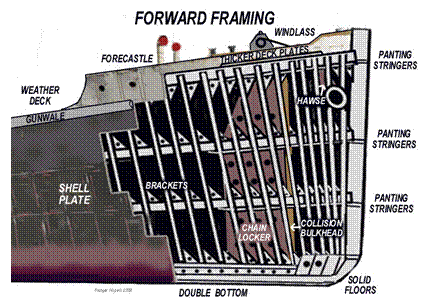
Steel construction - shell plating and decks
- The decks,
bottom and side shell plating form the watertight skin providing buoyancy and longitudinal
strength. While some old timers are still around that were built from iron
plates riveted together, modern vessels are all of steel plate. The steel shell
plating is built from many welded strakes
(sheets). The greatest bending stresses are experienced along the weather deck
edge that is also subject to impacts when berthing. Here an additional
longitudinal member called the gunwale
can be fitted. Deck plates are typically supported by deck beams. In larger
vessels those beams may be supported by longitudinal girders.
Additional strengthening is provided on deck where heavy
loads over a small area (point loading)
may be anticipated. Such
areas include the bases of deck machinery, hoists, masts, helipads and high
weight cargo stowage zones. The weight of containers is transmitted through the
stacking points at each of the four corners. Incorrect stowage of high density
cargoes will cause distortion of the ship’s structure. The vessel’s loading
plan will provide information regarding load limited areas. Sensitive deck
zones must be painted yellow with “do not stow here” or with the maximum load
limit stress in kilo newtons.
Steel
construction - superstructure - The superstructure describes the major
construction above the freeboard deck that usually provides deckhouses, accommodation,
stowage space and work stations. Structural discontinuities
(sharp corners) that could result as the starting points for cracks are avoided
by designing the superstructure in curved rather than abrupt terminations both
transversely and longitudinally. Where aluminium deck structures are mounted, gaskets
are used to provide insulation from the steel decks to limit galvanic
corrosion. The base of the superstructure is normally the boundary of the
watertight and the weathertight zones of the vessel, by virtue of the many
openings required here to provide access and ventilation.
Glass reinforced plastic construction
GRP or fibreglass construction uses a substrate of
hollow glass fibres that are covered with a mix of liquid resin, catalyst and
hardener. The resin mix impregnates the hollow fibres and hardens to form a
solid mass. A “one off” vessel can be built over a temporary former to create a
replica with a smooth internal surface but an exterior requiring fairing.
More usually however, a plug is created which in
turn is used to create a mould. Inside the mould, many identical copies of the
original with a smooth textured exterior can be easily replicated making the
process ideal for mass production.
Polyester resin is commonly used, but this has
inferior waterproof properties over extended periods of immersion (decades) to
the more expensive alternative of epoxy resin. The glass fibres can be sprayed
with the resin into the mould or, for course hand layup, chopped strand matting is cut to size, coated with the resin that
is subsequently dabbed or rolled into the fabric of the glass fibres. Woven
strands of glass called woven rovings
and woven rovings tape can be applied
where a finer surface finish is required or reinforcement is necessary. Other
fibres such as kevlar or materials
such as polyurethane fillets can be
glassed into the hull to improve structural qualities or weight in what is
called composite construction.
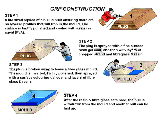
Standard layup techniques include solid resin/glass
and sandwiched foam (or balsa wood) between an inner and an outer glassed layer.
In sandwich construction the designer must include solid areas of glass or
packing pads for point loads such as a mast or winch, and for through hull drilled
holes such as for skin fittings. Stiffening is added to the inside of the hull
with glass floors and less commonly stringers and ribs may be fitted. Bulkheads
or even prefabricated fibreglass shower or whole galley units are installed and
epoxy resined to the hull. Plywood bulkheads must be fully coated with an epoxy
barrier coating (Everdure),
especially along the edges. Production vessels are universally made with a hull
section from one mould and a deck/superstructure section from another. The hull
and deck are then bonded, the unsightly join being covered with tape or a
gunwale.
Even without point thickening and reinforcement the
monocoque construction of GRP and ferro-cement vessels provides a seamless hull
of great strength, particularly when intelligent design of shaped deck camber,
topsides tumblehome and convex bow/stern sections are applied.
Weathertight
and watertight integrity
Weathertight doors and vents are fitted above the
weather deck into the superstructure to provide access and ventilation. They
will resist water ingress but if fully immersed, air will escape and water will
enter. Typical structures include a raised threshold
(step), splash guards and rubber seals with sliding or hinged doors. Vent
pipes may terminate with a swan neck or gravity flap valve to minimise rain or
spray entry. Such openings are best positioned in a shielded position rather
than facing the weather.
Watertight portholes, bow doors, side doors and
hatches are designed to provide watertight integrity by preventing water
ingress even if fully immersed. Watertight doors can be likened to valves whose
closing mechanism can be firmly seated onto a seal. Typical structures include
a raised threshold or hatch combing with rubber seals that mate with the
internal face of a multi hinged door. The hinge position can be adjusted to
ensure even mating as multiple dogs
(adjustable levers) clamp the door with its sealant strip. The seals should not
be painted. An alternative type of door slides vertically down into a tapered
base slot similar to a gate valve. Debris build up here can interrupt full
closure.

Doors and hatches can be tested for serviceability
by a chalk test (rubbing chalk on one
surface and checking that after closing its impression is fully transferred to
the mating surface) or by a pressure water hose test of 80 psi.
Internal bulkhead doors also enable passive fire
control by containment. Such bulkheads may additionally be coated with fire
resist paint or sheathed with steel or steel gauze. The bulkhead doors may be
edged with an additional intumescing sealing strip that expands in contact with
fire to further seal the door frame. Openings that allow the passage of pipes or
cables must be actually flanged to the bulkhead not just passed through a
drilled hole.
Strategic hull opening and bow doors must be fitted
with audio visual alarms at the helm station and internal subdivision
watertight bulkheads required to be closed at sea should be fitted with a
visual monitor.
10.3
Materials and preservation
Common
construction materials
Steel
Timber Glass Reinforced
Plastic (GRP) Aluminium Ferro-Cement
Timber
and timber products have unique qualities making it the most flexible of all
construction materials. If properly constructed and maintained timber vessels
routinely outlive their metal fasteners, notable examples still sailing after a
hundred years.
|
Timber |
|
|
Advantages |
Disadvantages |
|
Light weight for high strength |
Expensive - requires skilled shipwrights |
|
Aesthetically pleasing to human |
Aesthetically pleasing to vermin |
|
Corrosion resistant |
Rots |
|
Flexible and non magnetic |
Burns |
The
ability to weld new repairs as strong as or stronger than the old (even to
lengthen ships) has seen mild steel replacing both timber and iron plate as the
premier shipbuilding material. However it rusts rapidly
requiring rigorous surface coatings maintenance, even so few large steel
vessels are economic to keep at sea for more than thirty years.
|
Steel |
|
|
Advantages |
Disadvantages |
|
Cheap |
Corrodes readily |
|
One piece hull, no seams |
Heavy |
|
Not easily holed |
Inflexible |
|
Good fire resistance |
Magnetic - affects the compass |
The
resistant aluminium oxide that rapidly coats the bare metal provides decks and
topsides not requiring surface coatings. Its low position in the galvanic scale
promotes electrolytic corrosion when in contact with nobler metals such as
stainless steel or bronze.
|
Aluminium |
|
|
Advantages |
Disadvantages |
|
Light |
Expensive |
|
Does not rust - low maintenance |
Corrodes on lead, copper, bronze contact |
|
Easy to work |
Comparatively easily damaged |
|
One piece hull, no seams |
Low melting point - poor fire resistance |
Ubiquitous
for today’s small craft, production vessels are cheaply built with low user
maintenance requirements. Impact damage and osmosis are problematic after a few
decades, particularly for vessels built in the early days of the technique
(1970-80’s).
|
GRP |
|
|
Advantages |
Disadvantages |
|
Corrosion free |
Osmosis and chipping |
|
Easy maintenance |
Easily damaged on impact |
|
One piece hull, no seams |
Inflammable |
|
Cheap in mass production |
Skilled construction required |
A
cheap and solid hull built as a wirework basket and then finally rendered with
specialist cement screed. Some barges and floating wharfs are still floating
after a century, albeit looking shabby, a quality shared with some new amateur
built ferro-cement yachts.
|
Ferro-cement |
|
|
Advantages |
Disadvantages |
|
Cheap |
Chips easily |
|
One piece hull, no seams |
Skilled plaster of hull required |
|
Not easily damaged - easily repaired |
Heavy |
|
Fire resistant |
Magnetic |
Corrosion
and deterioration
Despite its resilient qualities timber will quickly deteriorate in the presence of fresh water or insect infestation. Two distinct types of rot can be identified, being wet rot that will be cured if the timbers are dried out and dry rot that is the product of persistent fungal infection requiring chemical fumigation.
Fungal infestation - occurs
when the moisture content rises above 20%. The fungi spread as airborne microscopic
spores so areas prone to condensation, freshwater leaks or low ventilation are
most at risk. Under the beam shelf along the deck edge meets all these
conditions. Warning signs of onset of fungal infection include:
Surface coating failure
A musty mushroom like smell
Softening, cracking or disintegration
of timbers
Fruiting fungal bodies,
incrustations or mycelium (white threadlike growths)
In
older vessels that have experienced alterations be wary of low points on the
deck where surface water accumulates. These points must be provided with drains
or scuppers.
Insect infestation - Timber is devoured by termites,
white ants and borers. The lyctus borer attacks
hardwoods with high starch content but many Australian hardwoods are immune. A
telling sign of infestation is a floury dust on the timber’s surface. Insects
can be effectively exterminated by fumigation with poisons such as pyrethrum.
Marine
Borers infestation - Crustaceans
such as the pill bug or gribble will attack the
softwood of timbers seen in old wharf pilings, but in southern waters the mollusc
called a shipworm or toredo is the most destructive. It larval stage is free swimming before
it attaches to any submerged timber, bores into it and grows as a worm. Beneath
the surface of the planking they can grow to over a metre in length and twelve
millimetres in diameter. They can honeycomb the plank with their tunnels to
completely destroy its integrity, unseen and unsuspected unless they break the
internal surface of the plank creating a spurting leak perhaps metres from the
initial entry point.
Prevention of attack is possible by impregnation of
the timber with creosote or chemical preservatives. Sheathing the underwater
hull with a fibreglass skin (dynal sheathing) is an alternative to the
traditional protection of copper plate over tar sheathing.
Infestation is best treated by thoroughly drying
out the vessel on the slip for several weeks and removing and replacing all
damaged timbers.
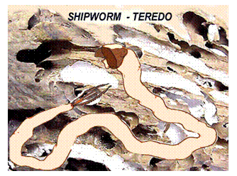
Timber
structural aging - A number
of common faults can occur including:
Nail
sickness – The
working of fastenings or nails in their pre-drilled holes along with the
corrosion of the fastenings themselves results in a loosely fastened vessel
described as being nail sick. Zones
that take a lot of fastenings and/or experience flex such as the hog, the sheer and the turn of the
bilge are particularly affected. The condition can give rise to a permanent
hog of the keel. It is unusual to find this condition when the traditional
practice of using treenails (wooden
dowels) for fasteners has been used.
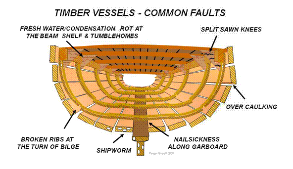
Broken
ribs - are
often found at the turn of the bilge at the point of a nail hole. Due to the
need to remove the deck and beam shelf to replace a whole rib it is common to
install an additional sister (partial
rib) with significantly less strength than the original.
Split
knees - the
economy of using sawn knees rather than grown or laminated knees often results
in splits along the grain, particularly around any fastening drill hole.
Caulking
damage - the convex
surface of the outer planking results in the plank edge seams being wider at
the outside than the inside creating a wedge shaped longitudinal seam. Because
of this it is possible to drive in the oakum
(seam caulking) and ram it home. If the back edge of the plank is broken away,
by too enthusiastic and inexperienced caulkers, then the caulking will be
pushed straight through and out the other side. There is no easy solution to
this common fault other than to router out a wider seam, slip in splines (softwood strips of western red
cedar) and dynal (epoxy sheath) over
the whole.
Preservation of timber - As
freshwater is the agent for rot in wooden vessels, make sure rainwater cannot get into
the timber. This can be achieved by two principle strategies:
Firstly ensure tight deck seams and engineer
solutions to deck areas where rain water puddles (drains and scuppers). Prevent condensation by ensuring
through ventilation, particularly when it is lying idle. Secondly, where rain or condensation
is unavoidable such as the insides of windows or under deck edges use
water-repellent preservative or surface coatings.
Water
repellents are deep soaking oils (such as Teak
Oil or Deks Olje) or epoxy soaks
such as Everdure. Both processes need
multiple coats paying particular attention to the end grain. Unlike the oil soaks,
surface coatings such as paint or varnish need to be fully sanded back before
reapplication with at least a primer, an undercoat and twin topcoats of
suitable marine and UV resistant quality.
Fungal
infection can be controlled with a water soluble preservative in the bilge of
0.65 Kg of borax and 0.45 Kg of boric acid in four litres of hot water. This traditional
mixture is non-corrosive and harmless to animals but check with your Marine Authority
that this meets the current environmental protection regulations in your
operating location. Regularly inspect your vessel’s timbers for decay and if
found act at once using the recommended proprietary preservative or poison for
marine insects extermination.
Deterioration of metal
Corrosion is indicated by the wastage and
decomposition of metals by chemical attack or by electrochemical reactions. Hence
it is the result of either chemical corrosion or electrochemical corrosion.
Chemical corrosion - Solutions
of acid (such as sulphuric acid and hydrochloric acid) or alkali (such as
caustic soda and lime) dissolve metal by chemically combining to form oxides,
other compounds and gasses. Typical areas of attack are at the engine room battery
banks, in storage cupboards and toilets (leaking cleaning products) or where hazardous
cargo packaging is breached. Great care must be taken in clean up due to the potential
for personnel injury and environmental damage. The chemical’s Hazardous
Material Data Safety Sheet must be consulted for the appropriate first aid
response and emergency management schedule. The IMDG Code also contains this information.
Electrochemical Corrosion - Electrochemical
corrosion is caused by electrical currents
flowing between physically close but galvanically dissimilar metals when both
are bathed in an electrolyte. (See pages 142 and 164). Saltwater plays the part
of the electrolyte and the steel hull the part of the anode. A small current
will be created as the bare steel is stripped and redeposited as rust at the
edges of the paint chip. The Galvanic
Scale of metals shown below indicates the comparative reactivity of
differing metals, and their differing readiness to corrode.
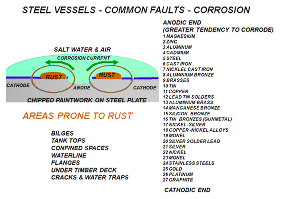
Note that all the corrosion resistant marine
grade metals and alloys that we use for fastenings and utilities (apart from
aluminium) are closer to the cathodic end of the scale than steel. On exposure
to air aluminium rapidly forms an aluminium oxide coating that is very resistant
to corrosion. Copper
is a ductile metal (bends easily
without breaking) that is used for nails. Brass is an alloy (mixture) of copper and zinc used for handles, hinges and
wood screws. Although it is partially resistant to corrosion, over time the zinc
will leech out of the screws making them brittle and easily broken. Over long
exposure to the marine environment bronzes are superior to brass. They are
alloys of copper and tin with traces of nickel. Other metals can be added with
bronze for specialist uses such as in manganese bronze bearings and annular
nails (of phosphor bronze). Stainless steel is available in many grades, but
the high nickel content marine quality of SS
603 does not rust and is non magnetic. It is however very brittle and will
not bend readily without snapping.
If two galvanically dissimilar metals are placed
together in an electrolyte, it is the one at the anodic end of the galvanic
table that will corrode with material from it migrating to the cathodic end (to
the more noble metal). Hence the use of a sacrificial
anode made of zinc is fitted near the costly bronze propeller, bearings and
stainless steel shaft to corrode in their place. It must also be noted that
where, for instance, a stainless steel shaft is selected to run in a bronze
bearing the cheaper bearing that will corrode not the more expensive shaft - a
better result than if the selection had been reversed.
Preservation of metals - Corrosion is controlled by
addressing electrolysis and/or by the use of surface coatings.
Sacrificial
anodes - are the tried and tested means used to address electrolysis.
Usually sacrificial anodes of zinc, but recently aluminium alloy, are available
in a variety of shapes and sizes including those dedicated to clamp around
exposed shafts and to fit as terminals for propellers. It is vital that the
anode makes electrical contact with the hull so it must be a clean metal to
metal initial fitting. Clearly anodes should be masked off on slipping and not
over painted with anti-fouling. Don’t forget to unmask them before launching. Lead
contacting an aluminium vessel will cause rapid hull corrosion. Lead based
paints must never be used on aluminium hulls and all non aluminium skin and
deck fittings must have gaskets to prevent electrical contact.
Larger vessels may also be fitted with an impressed electrical current network of transponders on the bottom of the hull designed interrupt the electrolysis process.
Surface
coatings – rely on the bond between the paint and the surface so the
surface must be corrosion free, thoroughly
clean and degreased ready for the initial primer. Techniques are more fully
described in the following section on paints
and surface coatings.
Deterioration
of GRP
GRP is a comparatively new boatbuilding material that in the short term has shown itself to be remarkably free from the drudgery of continuous maintenance due to weathering as required by timber and steel construction. GRP may only need antifouling every few years and a polish every decade to look almost as good as new. However it requires good fenders and rope leads to limit abrasion damage and care to avoid impact with the consequent chips and radiating star cracks. Particularly in older vessels, it can suffer the consequences of poor design and inexperienced construction.
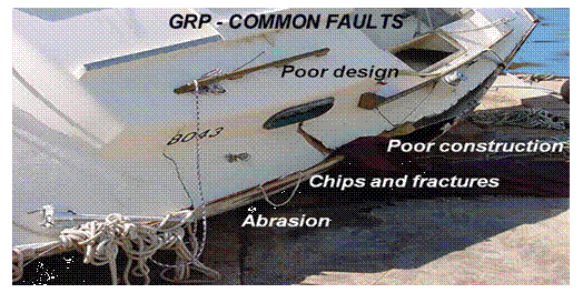
Design - and construction has come a long way since the earliest fibreglass vessels of the late 1960-1970s. Flex in sheets of fibreglass easily develop creeping fracture lines between a supported and unsupported edge. Wide T shaped terminals to posts and pillars are required to support by spreading the loads bearing experienced by large flat areas.
Some earlier designs assumed loads to be gravity produced failing to recognise that the stressed areas of the vessel at rest were not the same as those of the same vessel in its working state. Modern design has greatly improved structural performance and optimised accommodation space and layout.
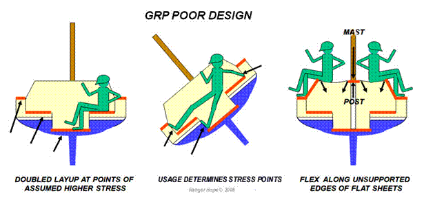
Early construction techniques did not fully appreciate the requirements for humidity control during the curing of the GRP process, or that polyester resins are not ultimately waterproof. The earliest beefy hulls built with cheap resin and gave way in the mid 1970-80s to a decade of soaring resin prices and thinner sometimes poorly cured hulls. A decade or two later it is not uncommon for this era of GRP vessel to exhibit the deterioration called osmosis.
Osmosis - occurs
when two differing concentrations of solutions that are separated by a semi- permeable
membrane develop sufficient difference in pressure to force particles from the
more concentrated solution through that membrane towards the less concentrated
solution.
Poor humidity control on build can allow moisture
to contaminate the resin so pockets of the resulting high concentration mixture
become encapsulated close to the gel coat
surface (the hull’s thin outer layer). The polyester gel coat becomes the semi-permeable membrane that is under pressure
from the underlying pockets of contaminated resin to burst through into the
salt water beyond. In fully developed cases the hull becomes full of blisters
and the gel coat breaks away leaving bare glass fibres to absorb seawater,
expose deeper encapsulated pockets and spread further deterioration.
Attempting to build an impervious surface
coating over osmosis blistering fails to address the root cause
that is the remaining pockets of contaminated resin trapped within the layup.
The blisters must to be ground out one by one with an angle grinder, the
hollows thoroughly washed clean and then fully dried. In serious cases it may
be necessary to have the gel coat shaved (with an electric plane like shaving
tool), the hull sprayed with water for many weeks to
purge it of resin remnants and then dried out for many months.
Once a clean dry hollow is prepared and
locally degreased with acetone, a marine grade filler paste of polyester resin
reinforced with fine fibreglass stands can be applied.
The hollow should be under filled so sanding
back with the inevitable exposure of fibre ends is not required. A reasonable
surface can be achieved by smoothing over some a temporary plastic sheet. When
the resin has cured a smooth layer of marine grade epoxy paste can be applied
and subsequently sanded back fair.
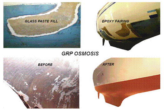
In completion to resurface a two pack epoxy paint spray coated will provide both a durable surface coating and a watertight membrane, albeit not as glass like as the original gel coat finish.
Glue, sealants, preservatives and surface coatings
(paints)
Glues and sealants - compounds
traditionally used as glue included water soluble vegetable bases, oil based rosin
varnishes or spirit based shellacs. While shellac
(ground beetles) and oil provided some waterproof qualities all these glues were
brittle when dried out. Organic oils and resins, gum arabic, bog pitch and tars
provided semi drying seals with greater flexibility and consequent sealant
qualities. In the construction and maintenance of a wooden sailing ship, tonnes
of pitch would be melted into the deck seams,
barrels of linseed oil putty and white
lead (lead oxide) mix pasted into every hull seam, creosote sloshed over any
unpainted timber that was not brightwork
(varnished) and very rope hanging from a forest of mast and spars was tarred.
Not surprisingly uncontrolled fire engulfed many ships.
Traditional modern animal glues and tars
have been replaced by chemical compounds of greater bonding strength, water
resistance and versatility or specialty so much so that for full product
information it is imperative both to read the products label and the material
data safety sheet. In a small vessel solvent stowage remains a major fire risk.
Always read the instructions carefully before opening the container.
Modern
PVA glue (polyvinyl acetate) used for
interior house joinery is not waterproof. Neither are the contact adhesives used for linings when rapid assembly is needed (both
surfaced are pre-coated before pressing together in situ). This adhesive bond can
let go in a summertime
heat wave. The development of water resist Cascamite like (melamine-urea powder/water
mix) and Cascophen like (resorcinol two pack resin/catalyst mix and
liquid hardener) provided a leap forward in marine and aviation timber bonding. The later in improved mix
shelf life, convenience of assembly and immersed bonding performance.
Two
pack polysulphide compounds replaced pitch for ship scale deck seam caulking with
the convenience of cold application, ability to sand back, over paint and form into
rubber like gaskets. Oil mastic sealants (that skin over but do not dry) have
been superseded by extremely flexible cartridge applied silicon sealants
(cannot be over painted) and polyurethane sealants (can be over painted). The
boundaries between glue and sealant are now indistinct with adhesives like the Sikaflex
range for specialist applications, and the West System merging timber build, epoxy
resin bonding, filling and final surface coating.
Preservatives - The greatest enemy of timber is rot
caused by fresh water. A soak in a preserving Teak oil or Deks olje)
or an epoxy soak such as Everdure is
effort that will be rewarded. Both processes need multiple coats paying
particular attention to the end grain. If possible, sit the end grain in a pot
of oil to fully soak. Unlike surface coating that requires sanding back between
layers, soaks only require a wipe back sufficient to key the surface. To
preserve the historic vessels SVs Mary Rose and Batavia specialist silicon
epoxies were sprayed over them that wicked up into the damaged timber fibres to
set hard.
Proprietary
timber preservatives contain poisonous and/or carcinogenic copper sulphate and
arsenic so they should be used with extreme care. Fungal infection can be
controlled with a solution of borax and boric acid described earlier in the
timber deterioration section. Oxalic acid
is affective in cleaning up beech decks but check with your Marine Authority
that any chemical used meets the current environmental protection regulations
in your operating location and plan to avoid any run off into the watercourse.
Surface coatings (paints) - paints are made from pigments and
drying agents mixed with a solvent. For
cleaners and solvents marine paints use water (acrylic paints), white spirit or
turpentine (oil based paints), or acetone thinners (two part epoxy paints). Oil
based paints are usually successful if over painted on top of an acrylic
undercoat - the opposite is rarely successful.
Specialist
paints use custom ingredients such as marble
dust for ultra violet resistance, oils
for flow qualities, metals for corrosion protection or
a catalyst to prompt the reaction process.
Specialist application paints include:
Anti-corrosive - used
on metal surfaces to prevent corrosion
Anti-fouling - used
on hulls to prevent marine organism growth
Barrier coatings - to
over coat differing paint systems without sand blasting back to bare surface it
is essential to apply a barrier layer between the old and the new. With
differing anti-fouling systems the remnant solvents can interact so reducing
the surface concentration of the active anti-foul ingredients. Similarly, twin
pack over layers may chemically attack single pack under layers.
Heat resistant - of
aluminium and graphite
Fire retardant - that
give off gasses as they burn to smother localised flames
Primer - the
initial surface coat that may contain anti corrosive metals
Quick
drying - for
intertidal applications
Non skid - to
prevent slippage in key zones
UV resistant -– particularly
for brightworks (varnish)
Surface preparation - is the
key to a lasting paint job. Timber must be scraped back and abraded to a solid
surface. A sanding sealer is often
used to fill the grain and give a better bond to the timber. On steel hulls old
paint and rust is first removed with a rattle gun or sandblaster. Persistent
low spots may require wire brushing or abrasive disc grinding back to bare
metal. When all paint and rust is removed a degreasing agent such as Prepsol is used to wipe down the hull. On
fibreglass vessels an acid etch primer may be required
to give a key for subsequent over coats.
Paints can be applied by brush, roller or spray
gun. Use the largest brush you can reasonably handle with a liner brush handy
for finishing to a fine edge. Quality brushes produce quality work, but with
some two pack processes it is impractical to clean a brush without using
buckets of thinners costing more than the brush, so a disposable may be more
economic. In all cases you should refer to the manufacturer’s instructions on
the recommended procedure, materials and safety precautions. Safety
information is also available in the material data safety sheet. Paint
instructions will include the acceptable temperature and humidity range for
application, the thickness required for each layer and the maximum/minimum over
coating time period. Minimal paint regimes will require at least a primer, an
undercoat and two top coats.
Paint is expensive - do not waste it. Prepare in
advance a convenient access to the whole job, mask off splash zones and only
mix up sufficient paint for what can be achieved before it begins to harden,
particularly in hot weather. Have solvent and clean up rags ready in advance
and disposal plan for the rubbish. On commercial jobs a quality control procedure
will require an accurate log of instrument readings to be maintained
(ultrasound, thermometer, and dewpoint) and volumes applied.
10.4 Slipping
operations
Slipping
methods and devices
A variety of methods and devices can extract a vessel clear of the water to enable out of water surveys or repairs, these include:
Careening - requires driving the vessel ashore to gain
access to the underwater hull. This procedure is rarely attempted except in the
remotest of areas with no slipping facilities or in the case of a dire
emergency. Environmental considerations must be addressed.
Ideally a flat sand or mud beach or river bank clear
of obstructions is selected when the tidal range is greater than the vessel’s
draught. This will usually mean a position parallel to the water’s edge where
the incline is least steep. Care must be taken that the vessel does not become
be-neaped (caught in the monthly tidal cycle when progressive lower tidal
heights occur). Grounding in part ballast will give the flexibility to settle
the vessel at a chosen point by pumping onboard or pumping out to float free.
The vessel should be adequately propped to remain safely upright or at least heeled
over away from the direction of the next rising tide. If the lower side faces the incoming tide and its
incoming waves the vessel could flood before the rising tide can lift her.
Heaving
down - the
vessel is heeled over while afloat using tackles acting on its mast from the
shore or another ship. While the chances of hull grounding damage are less than
careening the underwater area exposed is less and the repair crew must work in
the water.
The floating cradle (patented slipway) - is a set
of railway tracks fixed to a sloping base extending from deep water to above the high
tide level. A cradle (wheeled
carriage) with adjustable vertical arms runs on the tracks and supports the
vessel’s hull as it is winched clear of the water. Multiple carriages can be
linked together to form a cradle appropriate for the size of vessel. A
pollutant trap is incorporated to trap sediments and potential spills.
Smaller vessels may only need two cradle beams to
support the keel but with larger vessels the exact keel shape must be known to
the slip master so that keel blocks and packing pieces can be set up give
continuous support. Plans or photos are a great help as he/she places a taut
piano wire over the cradles length and places packing timbers to the calculated
distance below the wire. Often a final crushable plank of soft timber is placed
as the uppermost packer just in case the measurement is imprecise.
The vessel is driven or warped onto the cradle and
secured with springs. The vessel’s trim is sighted to make sure that it is not
listing as the adjustable arms are wound inwards to support the gunwales. As
the vessel settles onto the cradle, divers can check that the slip master has
got the packers right, or alternatively wedges can be inserted as required. The
cradle is slowly winched shoreward. Once the vessel and cradle are winched
clear toms and shores (support posts) can be positioned under hull overhangs and
at the turn of the bilge. A safety securing chain is attached to the cradle and
the slip master removes the docking plugs to drain remaining bilge water. This
potentially oily water must be drained into drums for proper disposal. The
docking plugs remain in the possession of the slip master who must re-insert
them as the final check before re-launching can proceed.
The travel lift – The
travel lift enables a rapid lift at any state of tide and can move the vessel
to any position on a hardstand for propping. Unlike the patent slip that is
burdened by the slipped vessel until its re-launch, the travel lift can execute
as many lifts as there is hard stand space available. Originally for small
operations, that shown below courtesy of Sydney City Marine has a 100 ton
capacity.
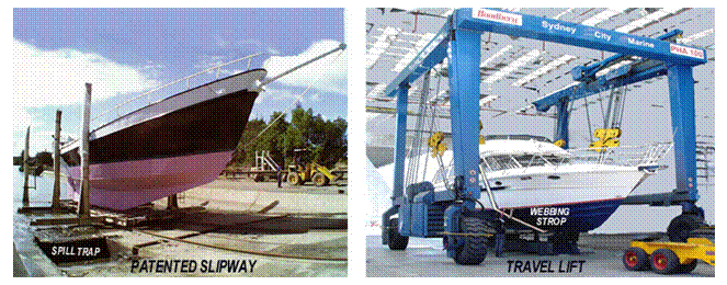
The travel lift can be driven out over a purpose
excavated narrow dock. Twin webbing strops hang down into the dock and the
vessel is driven into position over the top of them. The strops are then hauled
up by powerful winches. The positioning of the strops is critical, needing a
skilled travel lift operator. They must be placed so the load is evenly shared,
but also close to the bulkheads to prevent crushing the hull, and away from impellors
or transducers that are easily damaged. If all is satisfactory on inspection
after a partial haul then the vessel can be fully hauled clear of the water and
driven to the desired location for propping and stowage.
The dry
dock - The dry
dock or graving dock is created by excavating a short canal (dock) into the
river bank. It has a concrete floor gently sloping down towards the entrance
where fixed lock gates are positioned over a sunken sill. Alternatively a caisson gate (a submersible gate) can be
towed into position, sunk so the entrance is fully sealed.
The dockmaster sets up keel blocks the entire
length of the dock’s floor to support the intended vessel’s keel. Once the
vessel has been warped into the dock it is positioned over these keel blocks,
the gates are closed and the dock water is pumped out, back into the river. The
mounting pressure of the river water keeps the gates ever more tightly pressed
against the sill and frame. To open, the the dock has to be re-flooded to
equalise the pressure on both sides of the gates or caisson before either will
open.
As the dock empties the stern touches the keel blocks
first (called seeding the keel). At
this point divers will be sent down to ensure that the vessel’s keel continues
to seed fully supported all along its length. As the water level continues to
drop bilge blocks or side blocks are built up and wedged tight. At critical points support props
are also wedged under the hull. The sides of the dock are constructed in tiers not
only to provide several levels of access to support scaffolding but also for
side shores that can easily be positioned at various heights along the vessel’s
sides. After inspection, repairs and cleanup the launch is the reverse
procedure.
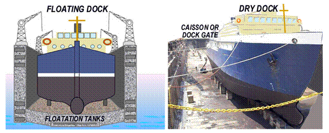
The floating dock - The
floating dock acts as a mobile dry dock that can be moved to the ship rather
than vice versa. It consists of a bottom platform built over a floodable double
bottom tank. The two side walls act as side tanks that can also be flooded.
The floating docks tanks are flooded so it sinks to
a pre-determined level. The vessel is warped into position and support jacks
are pressed up to support the length of the keel and turn of the bilge. Great
care has to be taken to ensure even loading and stability. As the tanks are
slowly pumped dry the vessel and dock rises clear of the water. Side shores are
wound in from positions embedded along the side walls. After inspection,
repairs and cleanup the launch is the reverse procedure.
The ship transporter - The
floating dock principle has been developed to its ultimate conclusion with the
ship transporter that is able to be submersed below other ships, oil rigs or
other structures and then refloated to pick them up as cargo to deliver them
worldwide.
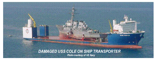
The super yacht industry is served by ship
transporters carrying dozens at a time of these small ships to their seasonal
cruising grounds. Though high cost, it can be less than the fuel, crewing and
stores required for a super yacht’s self propelled passage. It is also faster
and can avoid the need to slip the vessel for repairs and maintenance on route.
The synchrolift
- The
synchrolift or ship lift is created by excavating a short canal (dock) into the
river bank. A platform is suspended from the dock’s side walls that can be
lowered or raised by banks of synchronised winches.
The dockmaster sets up keel blocks the entire
length of the platform’s floor to support the intended vessel’s keel. Once the
vessel has been warped into the dock it is positioned over the platform, cradle and keel blocks, and the powerful
winches wind all clear of the dock water. As the dock empties the stern touches
the cradles keel blocks first (called seeding
the keel). At this point divers will be sent down to ensure that the
vessel’s keel continues to seed fully supported all along its length. As the
platform continues to rise bilge blocks or side blocks are built up and wedged tight. At critical
points support props are also wedged under the hull.
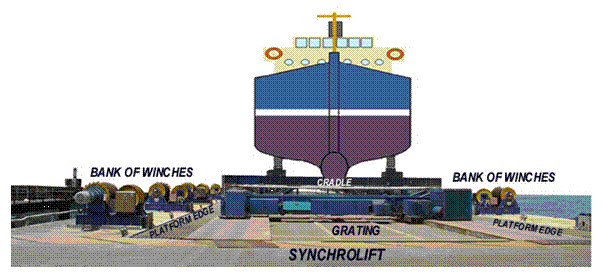
The lift shown above can accept vessels of up to
800 tonnes. Once the platform is level with the hard standing of the ship yard the
cradle and vessel can be hauled clear so the platform is free for another lift
and the vessel is under cover.
The slipping of a vessel is expensive and fraught with dramas unless well planned, organised and executed. The reason for slipping and therefore the priority of works must be well understood by all. This will normally be in consultation with the survey authority and according to the survey schedules previously discussed from pages 8-12.
Job sheets - must be drawn up in advance to ensure that the inspection, repair and compliance re-inspection can occur within the time frame of the slipping. If the substance of works are known in advance then labour, tradesmen, the repair materials and the access scaffolding can all be ordered in advance and be on site when required. Areas that require repair should be discussed with the dockmaster so props and blocks are not placed in the way.
Structural concerns - When
slipped the weight of the entire vessel will be supported at a few localised
points. It is clearly better to slip with empty tanks than with full ones,
though half full tanks present issues of free surface risks. If the support
points are chosen well, under bulkheads, frames/floors or other strong points,
the vessel will have sufficient strength to withstand the localised stresses. Pay
particular attention to the position of hull fittings such as keel coolers,
sounders, log and sonar transducers that could be damaged and tell the dockmaster
of your concerns.
With timber vessels there is the potential for a
slight change in shape of the vessel sufficient to jamb wooden doors and
drawers. If these need to be opened for access or works make sure all are so
before slipping, and re-opened before re-launch.
Stability concerns - as the vessel
is removed from the water its trim changes. Therefore
all potentially mobile weights should be lashed down or unnecessary weights
removed. In changing trim, any tanks that are inter-connected may result in
syphoning through the equaliser valves. Close them as soon as they are not
required.
The
patented slipway and travel lift constrain the vessel with arms and webbing
strops, but other methods can be more problematic. The stern area seeds first,
rising higher than the stem as the water recedes in the dry dock or on the
synchrolift. The weight distribution of the vessel changes and can
significantly raise the centre of gravity of the vessel. In the process of
repairs new materials to install and waste removed tend to build up on the
decks awaiting completion. Often large low components such as engines, chain
and ballast may be entirely removed. These changes can reduce the overall
stability of the vessel with disastrous consequences.
Crewing concerns - Your crew will be well drilled at the normal operations of the vessel, but not necessarily in the heavy industry environment of a busy shipyard. They will need induction for appropriate risk management including PPE’s, manual handling and use of power tools.
Slip and splash procedures and summary
checklists
The procedures must be customised for the slipping method of but generic checks include:
|
Step |
Actions when slipping |
|
1 |
Negotiate the plan with the surveyor, dockmaster
and crew. |
|
2 |
Empty or press full tanks and avoid liquid
transfers during slipping. |
|
3 |
Lash down or secure all loose gear. |
|
4 |
Trim the vessel with no transverse list. |
|
5 |
Trim the vessel to seed by the stern close
to the line of the support blocks. |
|
6 |
Shut down all machinery not required and
close sea cocks. |
|
7 |
Ensure the vessel is supported and stable
on all the support blocks. |
|
8 |
Connect safety chain when slipped position
is reached. |
|
9 |
Fit props to support overhangs and turn of
the bilge. |
|
10 |
Check for hull weeps, remove docking plugs
and record their placement. |
Precautions
on the slip - Ensure
that pollution and waste management controls are in place before water blasting
the hull. Provide safe access and appropriate Ppes. While ashore the vessel may not be able to fully utilise its fire
fighting system, so run hoses to the shipyards fire hydrants and position fire
extinguishers at accessible points.
If tanks or void spaces are to be opened and inspected then isolate the tank’s services, purge, vent and arrange issue of a confined space gas free and permit to work certificate. If welding or cutting are planned then a permit for hot works will be required.
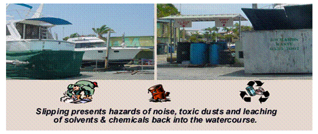
Transducers and anodes must be masked off as should anywhere where drips or over painting could reach, as it almost surely will. The maintenance and repair plan will drive the schedule, examples of which are discussed in the following section 10.5 Maintenance, inspection and repairs. However, because of drying and over coating time frames the painting regime is usually the critical determinant of when the vessel is ready to splash (and how many extra days of fees become due to the shipyard).
|
Step |
Actions for splash |
|
1 |
Confirm
the paint is dry and transducers/anodes
are un-masked. |
|
2 |
Re-fit docking plugs, check that skin fittings and intake gratings are replaced. |
|
3 |
Check that the anchors and chain are secured but ready to go. |
|
4 |
Remove
any tools, equipment, scaffold, shore
power and remove safety chain. |
|
5 |
Establish the same stability and trim conditions as at slipping. |
|
6 |
Check the slip is clear and sufficient tide has flooded to float. |
|
7 |
Check for leaks at sea suctions and discharges, side valves and stern gland. |
|
8 |
Test that the bilge and deck hose system is in working order. |
|
9 |
Test that the steering system is operating correctly. |
|
10 |
Open the salt water cooling sea suction valve and start the genset. |
|
11 |
Open the salt water cooling sea suction valve and start the engine. |
|
12 |
Check both for discharge overboard. |
|
13 |
Allow engine to idle for a short period. |
|
14 |
Check ahead and astern and depart the cradle. |
10.5 Maintenance, inspection and repairs
Maintenance
The value of maintenance is to ensure the continuous trouble free operation of equipment for the maximum duration before the expensive replacement with new is required. Daily use equipment is monitored in the pre-departure checks and obvious symptoms usually indicate when servicing is needed. Maintenance records not only schedule precautionary servicing but also tell a story of performance trends. However, emergency equipment may not be used in anger for years if at all. Such equipment, sitting in its highly corrosive marine atmosphere, cannot be relied upon to work when needed unless test operated as part of the maintenance schedule.
Maintenance schedules are also one of the essential safety management procedures that aim to identify hazards and reduce risks. A fuller description of example schedules is found at Section 1.2 Survey Page 8, the following information concentrating on methodology.
Maintenance records - may be kept
by a number of methods including:
Verbal, or scribbled notes - unreliable and do not capture
performance trends
Chalk or white boards - visible but
impermanent
Loose leaf record sheets - entered into
a folder on completion but subject to loss
Card systems - data cards recording servicing for
each piece of equipment
Maintenance logbooks - effective tracking & diagnostic books
that don’t go missing
Computer data bases - facilitates cross referencing but
unavailable at sea
Most vessels use a maintenance log book with a chalk
board to highlight regular servicing due date items (such as oil change,
coolant/fuel additives) and current status (such as fuel stowed and
pre-departure draught marks). Whatever method or combination of methods you adopt, it must be clear,
concise and accurate.
Maintenance checks - can include:
Primary consumables - Pre-departures, such as fuel, gas, fresh water
Ancillary consumables - Pre-departures, such as lubricant, coolant, electrolyte levels
Performance - Start up such as power, flow rate, pressure checks, brightness
Diagnostic indicators - Operating such as gauges, noise, exhaust
Service items - Filters, belts, globes, sharpening, replacement impellers
During this process, it may become evident that some
equipment is:
Loosing
performance or becoming dirty.
Operates
ineffectively or inoperative.
No longer fit
for the purpose due to many defects or many anomalies.
The development of these problems must be reported to the chief engineer or master/owner to ensure timely repairs/replacement. Let everyone know if equipment is removed or unserviceable by tagging.
Inspection
While the term inspection can be used in a general sense, it is useful to distinguish between visual inspection, examination, survey and audit. The defined use of those terms would be:
Visual inspection - A thorough visual check of the visible parts of equipment
Examination - A thorough visual and performance testing of accessible parts
Survey - Dismantling, measuring, performance testing and reassembling
Audit - Cataloguing the organisation’s resources and their functionality
The obvious purpose of inspections is the identification of faults to promote timely
repair, so maintaining equipment readiness. The process is continuous, but
there are levels of thoroughness that are appropriate. Pre-departures checks will include visual checks of the overall
readiness for the operational requirements. It might be at the visual inspection that a failure or
potential for failure is identified. This would require an examination to resolve the problem and mend the utility. Normally,
the more complete general examination
of utilities will await the maintenance schedule and its list of weekly,
monthly, three monthly and six monthly jobs. Others jobs will be determined by the manufacturer’s recommended maintenance schedules.
When
all the cleaning, maintaining and servicing has been completed, you must ensure
that the item of equipment works satisfactorily, to the standards, by testing. The
two basic strategies for testing are:
Proof tests - As its name suggests, proof testing is putting the equipment under load pressure and seeing if it is up to the strains of service (in fact, usually considerably more than would be encountered during normal use). An example would be a bosun’s chair and lift that Marine Orders 32 (Cargo Gear) specifies should support four times the intended usage weight. The advantage of this type of testing is its low tech confirmation of the fitness of the equipment for the user’s purposes. The disadvantage is that the equipment may well be destroyed, damaged or distorted in the testing process.
Specification (performance testing) - Usually requiring a degree of technical skill and testing apparatus to ascertain if the equipment meets the specification standards. Unlike proof testing, performance testing is not destructive. The specifications standards can be found by researching the:
The Australian Standards
National Standards (National Standards for
Commercial Vessels/Marine Orders)
Manufacturer’s Guidelines
Having identified the standard to which the equipment should match in performance, you check your manufacturer’s guidelines to identify the approved procedure of the testing.
Disassembly and reassembly - Specification testing often requires taking the equipment apart. Examples include removing a prop shaft to set up on a centre lathe for testing wear or dissembling a stainless steering ram and die testing for signs of fatigue fractures. Conforming to a procedure of disassembly will save a lot of grief when reassembling.
Safety
is a key issue and the importance of isolating power and fuel supply and
appropriate use of personnel protective equipment cannot be over stated. Good
lighting and a scrupulously clean dismantling area (perhaps a dust cloth below)
will limit the loss of parts that resist coming loose only to fly off and
disappear in the dirt. Contamination by oils and dirt is also reduced by
attention to cleanliness.
Using the correct tool for the purpose it was designed for will avoid burring and damaging nuts, and probably avoid slicing the skin off your knuckles if the spanner slips. Marine components are often corroded and can be extremely resistant to separate. It is not unusual to resort to ever longer spanners, bigger hammers, soaking overnight in diesel or even heating with a blow torch. In the increasingly wilder efforts and mounting frustration resulting from such situations, it is well to pause and reconsider appropriate PPEs (visor, boots, gloves, dust mask). In removing a reluctant propeller, it is wise to remove the retaining split pin and propeller nut, and then loosely refit the nut so that when the prop suddenly pops off the shaft, it does not fall on your toe.
Even though your manufacturer’s manual with its engineer’s exploded component diagram is a guide for reassembly, bearing wear often results in couplings and flanges needing to be reassembly as was. Before disassembly it is a good precaution to scratch aligning marks on both meeting surfaces. Likewise, a method of removing nuts, washers, springs, and laying them out in the order of disassembly will greatly assist reassembly.
Equipment may contain extremely complex assemblies. It is a brave or foolish person who attempts to dismantle a diesel rotary fuel pump and its many components. The questions must always be asked, “Have I got the skill and spares?” or “Is this a job for an expert?”
Test result records - As well as tracking maintenance carried out, we also are obliged to maintain a record of the equipment being tested before being put back into service.
Defective
equipment reports - The result of tracking is of great benefit to the
company purchasing officer. If items
manufactured by a certain manufacturer are consistently failing, it is
important to look for an alternate product. The company can purchase wisely when
such documented knowledge is readily available.
Gauges, measuring and testing tools
Inspection
and testing will require fine tolerance gauges and measuring tools. These are liable
to damage if bumped or dropped so they must be carefully stored, kept clean but
oiled and regularly checked against working standards of measurement (precisely made steel gauge blocks).
Getting the best out of tools is a learnt skill requiring practice. In use, holding
the test item and gauge in directly in front of you against a light background
allows you to take clear readings without errors
of parallax (reading at an angle).
Feeler gauges - are
used to measure clearances gaps between mating parts such as spark plug
electrode gaps, mating surfaces between couplings or valve tappet’s clearance.
When using the thinner gauges pull the gauge through a gap rather than push, to
avoid bending and permanently kinking it.
Depth gauge - is a stylus that can be inserted into a hole or slot, or between an edge and another surface.
Index or dial gauges -
are
used to measure the variation in diameter of material using a fixed dial/gauge
body with a plunger indicating its distance from a test piece. An application
will be a fixed gauge measuring the trueness of a propeller shaft mounted on a
centre lathe.
Screw
pitch gauges - for
finding the pitch of a bolt they consist of a series of marked blades with
teeth matching various thread systems. They are available for the common thread
metric systems of UNC (Uniform
National Coarse) and UNF (Uniform
National Fine) and imperial measures of Whitworth
(coarse), BSP (British Standard
Pipe) and BSF (British Standard Fine).

Profile
gauges or form -
are
used to compare shapes. They can be a fixed shape or profile, or an adjustable
type with multiple sliders as shown.
Radius
gauges -
check
internal and external radii. They are sets of marked blades with a convex (external) and concave (internal) radius of the same
size on each blade.
Callipers - are used to transfer measurement by closing their jaws between two fixed points. There is an internal and external type. The calliper gap is then compared to a graduated steel rule and the dimension read. It is bad practice to use callipers on a rotating work piece (on a lathe) as it will mark the work or wear the tool’s meeting surfaces.
Measuring tapes - a flexible steel tape is sprung loaded within a protective shell. The tape must be cleaned as it retracts into the housing to avoid subsequent jamming or the printed graduation marks being scratched away. These tools are not marine tolerant and will be destroyed with single salt water immersion. Regularly coat the tape with oil or WD 40.
Graduated steel rules - steel rules enable measure lengths to an accuracy of approximately plus or minus 0.5 mm. The end of the rule must be maintained with its edge square and sharp. A common error is caused by parallax error (not sighting across the rule at right angles to the graduations).
Vernier callipers - standard vernier callipers (with an engraved
graduation scale) measure to within 0.05 mm, though digital callipers (with an electronic graduation display) are
available with an accuracy up to 0.01 mm. Verniers
measure OD (outside dimensions) with
their main jaws, ID (inside dimensions)
with a pair of upper tangs and can be used for depth readings with the
protruding foot. Care must be taken to avoid wear on their
measuring
surfaces or bending the thin protruding foot. They must be stored lightly oiled
in a protective case to ensure that their accuracy is maintained.
The main arm of the tool consists of a metal rule of up to 250 mm long (the example shown below is160 mm) graduated in centimetres and millimetres. The main graduated scale indicates at its 0 mark the thickness to the millimetre (in the case shown a gap of a bit over 6mm). As the tool’s jaws are opened around an item to be measured, a sliding carriage moves with them. This carriage’s graduated scale is a vernier scale that enables accurate determination of that “bit over the millimetre”.
The lower carriage vernier scale is marked from 0 to 10 and divided into fifty graduations each representing 1/50th (0.02 mm) of the millimetre scale above. In the photo shown at a point of + fourteen graduations of the lower scale the marks on the main precisely align (28 aligns with 2). The tool is then reading 6 whole millimetres plus a bit that equals:
14 x 0.02 = 0.28 and in total
thickness 6 + 0.28 = 6.28
mm
Metric calliper shown below has a lower vernier scale marked from 0 to 10 (with fifty graduations) can be read without resorting to calculations but other models with a vernier scale of 0 to 5 (with fifty graduations) have larger marks display. However, in each case a graduation represents 0.02 mm of the whole millimetre scale above. Do pay close attention to the number of graduations on the vernier scale, 0 to 25 (with fifty graduations of 0.02 mm) are also common but other graduated tools out there are from the days of imperial measures with differing fraction intervals

Micrometers
- enable very accurate measurements of OD
(outside diameters) and length of smaller parts. They are available in various
sized frames (the bowed body) and
with imperial or metric spindle and
thread (adjustable rod) and barrel
(measuring scale). No matter what the frame
size and distance across the anvil
(the internal measuring surfaces) all are limited to the length of the thread
on the spindle. This is typically up to one inch or up to up to 25 mm. With
frames designed for over 25 mm work pieces additional 25 mm spacers are provided that can gap fill
and still allow the frames use for less than 25 mm work pieces.
The barrel scale measures from 0 to
50 in 25 graduated marks. When rotated twice the spindle widens by 1 mm. Each
graduation therefore represents 0.02 mm.
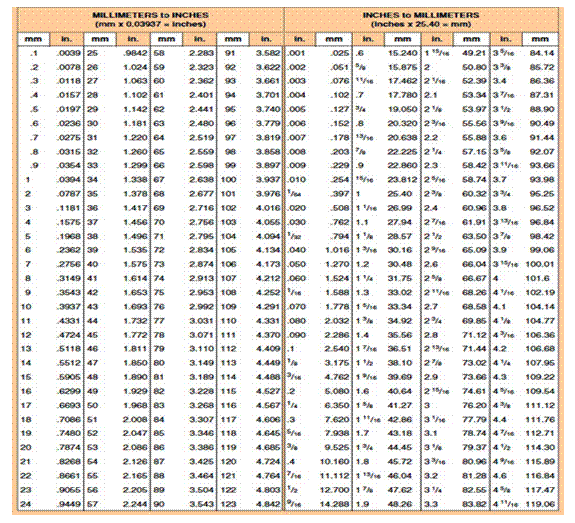
In using the micrometer, first wipe
the face of the anvils with a piece of clean cloth. The thimble (a torque set spindle winder) is turned until the anvils
fully close or close onto an inserted test spacer trapped between the rod and
anvil. As the torque setting is exceeded the sprung thimble assembly clicks
over as it declutches from the spindle.
A spindle locking lever is activated
as the thimble clicks to indicate declutching to prevent further movement of
the spindle while the micrometer scale is read. This test measure should read
zero on the scale, but due to wear on the spacers, micrometer or torque setting
of the thimble there may be a plus or minus scale error of 0.05 or more. The
force applied to the thimble to ram home the spindle requires a delicate touch
and if over done can alter the reading by 0.01 mm. So note both the appropriate
energy to exert and record the scale error to correct future readings.
This micrometer shown above has a frame enabling work pieces of up to 25 mm being measured. In taking a test measure between the anvils it is found that it is reading 0.003 mm when it should be 0.000 (measuring high). This is noted. A work piece is measured and found to have a thickness of 6 mm and a bit over. That bit over was the equivalent of winding the barrel scale past 6 mm once to the approximate mark of 28 (14 graduations x 0.02 = 0.28) with again a bit over. In the photo shown at a point of + thirty two graduations of the barrel scale the marks on the frame precisely align (32 aligns with 3). The tool is then reading 6 whole millimetres plus a bit that equals:
(14 x 0.02) + 0.003 = 0.283 and in total reading 6 + 0.28 = 6.283
mm
However, the micrometer was reading 0.003 high so the corrected thickness is:
6.283 mm – 0.003 = 6.280 mm
Disassembly and repair tools
There
is a right tool for every job that can make the difference between a simple
operation or a drama when alternative makeshift
contingencies are resorted to.
Operations, servicing and damage control - The slipping plan should identify what specialist tools or equipment needs to be on site. If forgotten, while on the slip access to tools, equipment are spare parts will inconvenient but not be over problematic. However, it does provide an opportunity to review the tool kit carried as may later be required at sea, particularly if new plant is installed. Most vessels less than 24 metres will carry a tool kit with spare parts for routine servicing and at best a work bench with some additional hand and portable power tools. Most vessels less than 35 metres will be better equipped with at least limited workshop facilities hopefully including a bench grinder, drill press, welding and even thermal cutting gear. The traditional saying that there is the right tool for every job is as true as the frequency of having to improvise when at sea. The skill of the marine engineer will be to ensure that the minimum required to complete routine tasks at sea is carried as well as sufficient to deal with emergencies to enable a safe haven to be reached.
Audit of the tools and spares carried should look at preparedness for:
Operations - are specialised operational tools readily available for routine operations, such as fuel sounding rods, filler cap spanners, LPG cylinders, hatch wedge mallets, anchor shackles, cargo hooks, locks and keys, etc.
Servicing - are adequate servicing tools and spares available for scheduled operations, such as changing oils and filters, fuses and breakers, belts and impellers, ropes and hawsers, wire cables and hooks, etc.
Damage control - are adequate operational tools available and stowed where they are needed in an emergency, such as fire axes and extinguishers, hull wedges and shores, collision blankets, wire cutters, etc.
That correct tool to include in the tool kit will be either a hand tool or a power tool (electrical, combustion or compressed air dealt with later on page 228) designed to optimise work performance related to work holding and forming, impact or torque, scraping or cutting, surface coating, or jointing.
Work holding and forming devices - These are fixed vices, machine vices, portable clamps and anvil formers. The two basic types of fixed vice are the soft jawed (wooden) carpenters’ bench vice and the cast engineers’ vice. The latter may have a mini anvil flat and/or horn. Clearly they must be well bolted down onto a stable bench or foundation. Disposable jaw covers can be inserted to avoid marking the work piece. Care must be taken not to damage the clamping thread when though drilling held work or from weld spatter.
Portable clamps include G clamps, long sash clamps, mole grips, plyers and sprung welding hand clamps. The latter can have surprisingly strong spring action that can bite.
The blacksmiths anvil is a heavy iron casting intended as a multi surfaced forming device for red hot metal pulled directly from the blacksmith’s forge. It has a squared body with a flat top for plannishing (hammering metal smooth) and forming angles in steel plate or bar. A tapered horn is fitted on one end for forming curves in bar, and at the other an extension has a number of sockets that will accept specialty formers. These are not usually carried on small vessels, in part replaced by mini versions or adaptions to the engineers vice.
Impact or torque devices - A number of impact hammer types are available including the heavy long handled sledge hammer, small lump hammer, the carpenters claw hammer (for extracting nails), the engineers rounded ball peine hammer, plannishing hammers and tack hammers for small work. In operation the best efficiency is gained by holding the end of the handle. For nail driving operations the head of the hammer needs to be kept clean to minimise glancing blows while for shaping operations the piene must be occasionally reground back to smooth to prevent marks being imprinted in the work’s surface. Flying splinters, sparks and being dropped onto personnel below are all risks with these tools.
The spanner improves the torque that can be applied to loosen or tighten a bolt. They are made in imperial measure or metric with the size stamped on them or sizes if they are often double ended. The size refers to the diameter of the bolt thread, except in the American system where AF is used (this is the distance across the flat part of the bolt head). The jaws of a spanner are often cranked at a slight angle to its body. Where access only allows minimal rotation of the bolt head, this enables the spanner to shift the bolt fractionally then to be turned over for another fractional rotation. Where access space is not a problem it is good practice to hold the spanner with the crank placing the spanner body furthest away from the operator. Not only does this provide better torque, but the operator’s grip is less likely to slip with a consequent bruised and bloody hand. Using the correct size of spanner is critical to avoid burring the bolt head or nut’s faces. Spanners are open ended or ring design, the latter more suited to tight access spaces and less likely to fly off of the sudden release of a bolt under pressure.
A variety of adjustable spanners are available including the stilson (toothed plumbers pipe wrench), shifter (with knurled screw jaw adjuster), mole grip and adjustable pliers. Ensure the best fit before rotating to avoid slipping and burring.
Barrel sockets are made in sets of imperial measure or metric with the size stamped on them. Typical wrenches (driving arms) are made with 1/4 inch, 3/8 inch and 1/2 inch or 6 mm, 10 mm and 13 mm driving pins. Though cheap socket sets are readily available, they break quickly and are a false economy. Various ratchets, extensions and offset drive devices can fit into the tightest spots that conventional spanners would never reach. Torque measuring extensions are available enabling assembly to a manufacture’s specifications.
If these cannot be determined at sea, disassemble with the torque wrench and record the measures for reassembly.
The screw driver is available for the common slot headed screws, phillips headed screws and hexagonal headed screws. Hand and power screw driver insert sets with custom tip bits and sockets are now common for a wide diversity of screw and bolt heads types.
An exact fit between screw head type and screw driver tip is essential, especially where a power tool is the driver. A variant of the conventional screw driver is the push spiral drive or yankee screw driver now largely superseded by the battery operated cordless screw driver or the pneumatic socket driver. The more robust impact screw driver works on the same principle that when belted with a hammer dives a spiral thread to rotate the screw driver bit or socket.
Scraping or cutting devices - Though in operation the distinction blurs between scraping and cutting the required sharpening angle of tool bits is quite different. Scraping tools require a very flat edge that may be improved with a burr. Their action is to tear a fine layer off a surface to leave a smooth finish. They should be applied to the work piece at close to 90º. Alternatively, cutters have a tapered sharp edge that slices through the surface and deflects the cut portion away for the cutting blade. They should be applied to the work piece at fine angles. Using the cutting blade at a skew will provide a greater length of blade edge to bear on the work piece with even better cutting effect.
Scrapers
include hand scrapers, finishing centre lathe tool bits, power timber planer
thicknessers, power routers and abrasive discs. Unless very tough material such
as high carbon steel or tungsten is used for scraper blades they will lose
their edge rapidly. Cutters include rasps and files, roughing centre lathe tool
bits, hand timber planes, saws, knives, chisels and oxy acetylene cutting. With
any cutting of scraping tool it is important that it is sharp. This is
particularly so with power tools that must never be forced.
Drills are essentially scrapers of hard materials with a cutting action on soft material. Metal drills are shaped with a flat edge to chip off material and remove it from the tip through the spiral flute. Wood drills have a sharper tip angle, and wood augers have a honed leading edge blade. Blade angle charts are available at your hardware store.
Surface coating or jointing devices - Surface coating tools are described at P 213. Jointing devices include mechanical types such as riveting, pop riveting and stapling. Thermal methods include arc welding, oxy welding and braising.
Hand tools and power tools - Clean up the work area so you are working on a dry non slip surface. The operator’s position is all important for the use of tools. You must be stable over the full passage of the tool over the work surface so that if there is a sudden release of resisting pressure you do not topple over. It is important to determine if the work of the tool is achieved in the push or return stroke for flowing movement, as it is to ensure that any cutting actions are away from the operator’s body. In works aloft or where tools can be dropped into inaccessible voids it is essential that lanyards (safety ties) be fitted to your tool belt. Sharp power tools are very important as over working a blunt power tool will lead to its demise or an accident.
Power tool electrical leads must be inspected and tagged at six monthly intervals, and be checked before every use for damaged insulation. Ensure earth and surge protection devices are fitted, and that the slipway power supply matches that of your power tool. Do not have cords lying on wet surfaces, wrapped around scaffolding or have large lengths coiled tightly during use. Support them above the ground with warning tape where required. Try to arrange for the cords of portable power tools not to lead to below your feet where you will be trading on them. Clear away waste, shavings and swarf as it builds up around the work piece. Always use personnel protective equipment with power tools.
Personnel protective equipment
Proper work wear includes wearing appropriate footwear, head gear, safety clothing and removing/mitigating long hair, jewellery and loose clothing. Safety ppes include hard hats, visors, earmuffs, dust masks or breathing apparatus, gloves, aprons, overalls, work boots and sun protection as shown below. Your crew will be trained in their job at sea not on the slip. Induction by safety briefing is required.
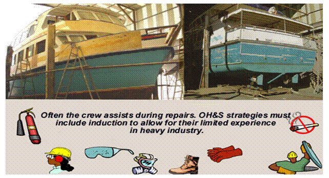
Repairs
Checking for hull defects – The corrosive effects of sea water and the
attack by marine organisms will cause deterioration in a vessel’s hull. The
build up of marine growth and flaking paint will be noticed as a reduction in
performance after time. The continuous minor impacts from flotsam will
contribute to defects requiring repairs to meet survey including:
Shell plating cracks, plank rot, worm or
loose caulking
Leaking shell plate or planks
Loose or corroded fastenings
Impact damage that distorts two or more
frames more than 25mm
Stern frame distortion or stern affecting tail
shaft or rudder alignment
Areas of corrosion including expired anodes
On coming out of the water the hull should be checked for the tell tale signs of exterior weeps from the bilge water. After pressure washing these points and other detected damage zones should be chalk marked for closer inspection. Sighting along the hull close to its surface will reveal any spots of unfairness in the plate or plank that may be due to detached or misplaced support structures below. The state of the anodes will indicate what new to order. Final arrangements for the surveyor inspection should now be confirmed.
Tail shaft inspection - Shafts should be withdrawn for inspection every 4 years (USL). If the vessel is slipped within that period it is wise to check the weardown of the aft bearing as shaft sag (due to propeller weight) increases stress in the shaft. The weardown is a measure of the sag (deflection). Increased vibration at the vessel’s stern and persistent stern gland leaks (despite adjustment) are symptoms of excessive tail shaft or stern bearing wear. If exceeded, the consequences include fracture of the shaft with propeller loss. Weardown allowance is determined by the manufacturer, but rules of thumb range from 3% of diameter due for replacement to 6% being condemned (3% of a 50mm diameter shaft is 1.5mm permissible movement within the bearing). The outer bearing can be checked on the slip, by lifting the propeller or inserting a feeler gauge between the bearing and the shaft. If over worn, the tail shaft should be removed for inspection and workshop repair. Sometimes the rudder will restrict the tail shaft from moving aft and will also need to be removed. This is described earlier in Section 6.4.
Propellers can be very heavy and have sharp
edges. As the propeller becomes free, it can quickly slide along the shaft causing
personal injury or damage.
To remove a large propeller
first fit lifting arrangements to support the prop. To remove a small propeller
remove rope guard and fairing piece from propeller nut, then remove locking
device and nut. The prop may be stuck fast on the shaft. That means that when
it does come off it may do so suddenly, so refit the prop nut and tighten for a
loose fit sufficient to stop the prop jumping off the shaft when it finally
becomes free.
To loosen the
propeller fit a puller or drawing gear (two or more long threaded
rods tensioned between a plate positioned forward of the propeller boss and a strongback (a solid piece of timber) aft
of it. Place the strongback over the studs
so that it bears on the end of the shaft and evenly tighten the nuts on the threaded
rods. At some point, the load will overcome the friction between propeller and
shaft taper and the propeller will dislodge. If the propeller remains seized on,
a sharp hit with a large hammer on the strongback can produce results. In
extreme cases, heat may be needed to break the corrosion seal.
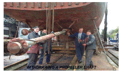
With the propeller
and the inboard shaft coupling removed and clamps on the stern tube, packing
and seals released, the tailshaft can be withdrawn. It will be heavy so strops
and lifting equipment will be necessary. It may be wise to erect a scaffold to
support the shaft as it is withdrawn and to guide it back in again when
re-installed. While the tailshaft is out any seals, bearings and packing should
be replaced.
The shaft is then
sent for inspection for wear and trueness on a centre lathe. It may also be dye
stained show up stress fractures. If there is minimal wear away not by the
bearings it may be possible to end for end the shaft and refit it. It is not
acceptable to weld on additional material and turn the shaft back to the
specified diameter. If anywhere over its length the shaft is over worn a new
shaft will have to be made up.
With the shaft drawn (removed) gear box to shaft alignment can be positively checked by stringing a taut piano wire through the dead centre of the outer bearing, the dead centre of inner bearing and carried on to the gearbox coupling. The gearbox coupling’s dead centre must accurately line up with the shaft coupling position (the inboard end of the taut piano wire). If the taut wire does not meet the dead centre of the gearbox coupling then either the engine/gearbox unit must be moved, or the outer bearing bracket moved (the latter being more problematic). The engine/gearbox unit position can be adjusted by loosening its mounting bolts to rotate the longitudinal alignment, and adding or removing shims (metal spacers) to lift/lower the gearbox and coupling for correct tilt and elevation. Reinstalling the shaft is the reverse of drawing, much assisted by the drawing support guides.
Re-packing the stern gland -
Packing material inside the stuffing
box of the stern gland partially seals water from entering the vessel around
the propeller shaft. Water is designed to enter the outer stern tube for
cooling and lubrication so a regular drip into the vessel indicates that it is
correctly nipped up and not over
tight. Some arrangements also have coolant water piped to enter behind the
gland and others grease nipples that can supply into the gland. This is
described earlier in Section 6.4. As the packing wears tightening the gland nut/nuts will not stop water
from pouring into the vessel. The stuffing box must be repacked and this is
most conveniently done on the slip. The procedure is as follows:
Remove nuts that
tighten the collet (gland packer
slide assembly) and withdraw it away from the packing gland. This will expose
any remaining packing. Using a fine hook pull out any remnant packing fibres from
the housing (back of the gland). Count
the number of remnant coils of packing (usually 3 - 4). Wipe clean to fully
exposed the shaft’s surface and inspect for any over wear that may require a
new shaft.
Select the correct
size of gland packing material. If in doubt as to the correct size then measure
the gap between the shaft and the housing. Prepare the packing by cutting it to
make coils of a few millimetres less than the shaft circumference. Each coil
must be cut obliquely at its ends to overlap rather than butt when wrapped
around the shaft. Cut 3 - 4 coils or the
same number of packing lengths that were removed. Lightly grease the shaft
surface and fit each coil over the shaft ensuring that the cut ends are
staggered. Though with worn systems it is common to see heavy greasing, this is
a mistake, particularly in sandy areas where the grease and sand form an
abrasive paste to exacerbate wear.
With all coils
inserted and pushed back into the housing, there should be 5 -15 mm under fill
that allows the collet to be slid back along the shaft and meet with the
packing. Finger tighten the collet tightening nuts. Ensuring
that the collet remains square on the shaft, continue tightening the nuts to
compress the packing until resistance is felt (about 20%) but the shaft can
still be turned by hand.
After relaunching
the gland should be inspected immediately and at ten minute intervals for the incorrect
conditions of badly leaking and heat of friction from an overtight gland.
By tightening or
loosening to correct to a condition of a slow drip and a cool bearing, the
inspection schedule can be eased back to daily pre-departure checks.
Rudder bearings - Steering and rudders with their common problems have been discussed in Chapter 5.4. The rudder itself must be able to turn reliably from 35º to 35º, and on the slip the opportunity arises to check wear and serviceability. Areas prone to deterioration are:
Shafts or pintles bearings wear
Rudderstock to rudder attachment
Erosion and corrosion of rudder nosings
Cracks causing leakage into hollow steel and
GRP rudders evidenced by leaks on the slip
The two common types of rudder are the heel supported and the hung rudder. The hung rudder may be semi balanced or balanced.
The heel supported or pintle type arrangement is securely mounted by bearings at the deck, under the hull and under the rudder at the heel or sole (an extension to the keel). The condition of the sole requires inspection for structural integrity, as does the condition of the pintle and its lower support bearing. Any weardown here can cause a drop in the position of the rudder itself with the possibility of its lower edge fouling the sole. The wear at the bearing points needs to be established either crudely by attempting to wobble it and measure bearing clearance with feeler gauges, or more precisely by pressuring the rudder with portable jacks at differing helm positions and recording the rudder stock displacement with a dial indicator. The dismantling of the rudder and sole assembly may be required to draw the rudder stock, though in some arrangements it is possible to loosen the deck upper stock, hull lower stock bearings and pintle bearing sufficient to slide the rudder stock past the sole. Over wear requires bearing or rudder stock replacement.
The hung type arrangement is checked for bearing and shaft wear in the same manner as above. Especially with the balanced type there is enormous stress where the rudder stock meets the lower stock bearing. Constant flex at this concealed point within the bearing can weaken a stainless steel shaft by progressive fracture, only to be revealed when the rudder and lower shaft fall off. Fortunately, withdrawing the rudder stock is much easier with this type as usually only the tiller has to be removed for it to fall away, so this precautionary inspection should be carried out every four years.
Deck equipment -
Deck equipment includes the machinery, fittings and anchor chain as well as
standing rigging and running rigging and is fully described in Chapter
4. Deck machinery is robust
but it is exposed to weather, can be mishandled, overloaded and can suffer poor
maintenance.
Ground tackle - The anchor cable should be removed from the
vessel every 4 years (USL), ranged on the ground and inspected for
deterioration and serviceability. Chain wear of more than 10% in link diameter
is condemned. The swivel pins of anchors must move freely. The chain locker
should also be inspected (a confined
space) as well as all associated fairleads, rollers, hooks and restraints.
Common service and repair issues for windlasses include corrosion of supporting
deck, bent shafts due to overloading (from allowing the load to be carried by
the windlass at anchor) and lack of maintenance resulting in bearing and shaft
wear, worn linkages and brake wear.
Lifting equipment - Common service and repair issues for
winches include corrosion of supporting deck, bent shafts due to overloading,
standing rigging corrosion and running rigging wear.
Windlass/capstans, winches and other machinery must be serviced
and repaired to standards including those listed in Marine Orders 32 Cargo Gear and the NSCV Part C Section 7 Subsection 7D-Anchoring and Mooring
Equipment. Older vessels
may comply with USL Code Section 9 Engineering.
It should be noted that lifeboat davits and other mechanical launching arrangements
are also deck machinery. The requirements can be found in NSCV Part C Subsection 7A-Safety Equipment. Older vessels may
comply with USL Code Section 10
Lifesaving Appliances.
Confined and void
spaces
It may be required that entry inspection and works are required in void spaces, holds, tanks or coffer dams that are not designed as a place of work where access is restricted - in confined spaces. Putting your head or upper body inside a confined space can be dangerous due to a number of hazards including fire, electrocution, noise, or obstructions, or even fatal if there is an insufficient or contaminated atmosphere.
Risks management – Confronted by a confined space the employer and employee have a duty of care to identify the hazards (what could happen), assess the risk (the likelihood, severity and duration of exposure to the hazard), develop a management plan and lastly monitor and review the adequacy of the plan. Consideration must be given to eliminating the hazard perhaps by not entering the tank at all, but instead using remote cameras and servicing equipment from outside the space. If the hazard cannot be eliminated then consideration must be given to minimising the risk by:
Substitution - by using
a safer working chemical or applicator (e.g. a brush not spray can).
Isolation - shutting valves that allow contaminants or services enter the space.
Engineering - detectors, alarms, lockout mechanisms and alternative entry point.
Administration - safe work practices including, training, tagging (recording workers movements in and out of the workspace), a sentry (person standing by outside to raise alarm), entry permits rules, signage and personnel protective equipment.
Rescue - suitable procedures are in place for rescue, first aid and fire suppression.
Risk increases with low visibility, extremes of temperature, gravitational hazards, room to move, nature of work (welding, electrical, or motive equipment), physical activity (worker’s fitness, skills and experience) and the length of time spent inside the space
To enter, a confined space an entry permit must be signed off by a competent person (trained and certified) who has ensured that all the steps of the written requirements of substitution, isolation, engineering, administration and rescue have been satisfactorily met. To ensure a safe atmosphere the steps may include that the space is purged. This may be done by filling and emptying with water or with an inert gas. The space will then have to be vented for a specified duration. Lastly a gas monitor must be lowered into the space for a gas free certificate to be issued for a defined duration. Additional permits may be required such as permit to work and permit for hot work.
Acknowledgements
References are
attributable to the USL Code, the National Standards for Commercial Vessels,
Australian National Training Authority’s Maritime National Module Learners
Guides, Caterpillar, GM Detroit, Bosch, Reece Plumbing Supplies, Wikipedia,
Norglass, and International Paints. Other sources include but are not limited
to;
H. Chappell -
Boatbuilding,
H. Chappell -
American Small Sailing Vessels,
P. Clisshold -
Basic Seamanship,
Basil Greenhill -
Merchant Schooners,
Kemp & Young -
Ship Construction,
H.J.
Pursey - Merchant Ship Construction.
In addition to the
sources quoted I thank Richard Sprogue, Vikram Malhourta, Harry Machin and Atef Jaber for their expert advice.


