MARINE
ENGINEERING - BASIC TASKS
(Contains extracts & edits of material courtesy of A.N.T.A. publications, update
version Ranger Hope © 2008,)
Operating Marine
Diesel Engines
1.1 Checks And
Procedures Before Starting Engines
1.2 Checks To
Be Made If An Engine Fails To Start
1.3 Warm Up And
Cool Down Periods
1.4 Engine
Overheating Symptoms
Slipway Work
2.1 Periodic
Maintenance And Survey For Commercial Vessels
2.2 Preparations And Inspections
2.3 The Function Of
Sacrificial Anodes
2.4 Measuring Sterntube Bearing And Tail Shaft
Wear
2.5 Opening Side Valves For
Survey And Maintenance
2.6 Checking Rudder
Stock And Pintle Bearing
Wear
2.7 Attaching The Propeller To The Shaft
Deck Machinery
3.1 Operation Of An Anchor Windlass And Cargo Winch
3.2 Dangers Of
Incorrect Operation
3.3 Routine
Maintenance
Operating Marine Diesel
Engines
1.1 Checks And Procedures Before Starting Engines
The
checks and procedures to be carried out before starting an engine depend on:
• whether the
engine has just been repaired or overhauled and
• whether you were the last person to
run the engine.
The
person with the Certificate of Competency to operate the machinery of the
vessel is the one who takes full responsibility and cannot transfer the blame
if something goes wrong. To cover yourself you must carry out pre-departure
checks and checks whilst the vessel is under way. The following checks cover
the engine.
|
ü |
Checks |
|
|
Ensure that all work carried out to
the engine has been completed and that there are no tools, materials or parts
lying on the engine. |
|
|
Ensure that there are no rags on the
engine, especially the exhaust area. Check the whole engine is free from fuel
and lubricating oil. |
|
|
Gear box is in neutral. |
|
|
Sea water strainer is clean and open
the sea connection valve and, if fitted, the overboard discharge valve.
Ensure there are no sea water leaks. If the
vessel has been on the slip, it may be necessary to bleed off any air at the
sea water pump. |
|
|
Water level in the fresh water
header tank and ensure there are no fresh water leaks. |
|
|
Condition of all hoses. |
|
|
Sufficient fuel in the fuel tank for
the intended voyage plus a reserve amount of fuel. |
|
|
Open the fuel tank drain valve and
drain off any sediment and/or water. |
|
|
Open the fuel tank outlet valve. If repairs
have been carried out to the fuel system on the engine, it may be necessary
to prime the fuel system and bleed off any air. |
|
|
If a water separator is fitted,
drain off any accumulated water. |
|
|
Check the movement of the hand
throttle. |
|
|
Check the oil level in the sump
shows full. In some engines, a hand priming pump is fitted so the system may
be primed and prevent the major wear that takes place on starting an engine. |
|
|
If the fuel injection pump has its
own sump, check that the level in the sight glass is at the upper line. |
|
|
If a turbo charger is fitted and has
its own lubricating system, check that the level in the sight glass is at the
upper line. |
|
|
Check that the batteries are clean,
charged, the electrolyte level is above the plates and the terminals are
clean and tight. |
|
|
If it is possible, bar the engine
over at least one complete revolution. This is
carried out to ensure there is no fresh water in a cylinder which could
hydraulic the engine. It is also to ensure the engine can turn over freely
and nothing has been left in any of the cylinders and all parts are back and
are in proper working order. |
|
|
Switch on power to the starter
motor. Give the engine some throttle. Engage the starter motor. The engine
should rotate and fire. |
|
|
Immediately check the oil pressure. |
|
|
Listen for any unusual noises,
especially hard metallic knocks. |
|
|
Check for fresh water, sea water,
lubricating oil, fuel oil and exhaust gas leaks. Ensure sea water is being
discharged overboard. The engine fresh water temperature will slowly rise and
stabilise at its operating temperature. The lubricating oil pressure will
drop from its initial starting pressure to its operating pressure. |
|
|
The revolution counter will be
indicating. The throttle should be increased and decreased slightly to check
its movement and that the revolution counter is functioning. |
|
|
With the engine at its operating
temperature, check the colour of the exhaust gas. Black smoke
indicates excessive fuel for the amount of air and caused by poor or
insufficient combustion or engine overload. Blue smoke
indicates lubricating oil is being burnt. White
exhaust vapour indicates water or moisture. It may be in the fuel, moisture
in the air or from cold cylinder liner bores when starting the engine. |
1.2 If An Engine Fails To Start
This
section lists some reasons for engines failing to operate correctly. There are
many possibilities, so discuss these with your facilitator. Use this section as
a reference guide for later use, particularly when next on your operating vessel.
Engine
Will Not Start Or Is Difficult To Start.
If
the engine does not start, the causes are mainly in the supply of fuel and/or
air.
Remember:
1. A full charge of air needs to enter the
cylinder.
2. This air must not escape as it is being
compressed otherwise insufficient heat is obtained to ignite the fuel.
3. Fuel must be injected in an atomised form
into the cylinder at a precise moment.
4. In addition, there must be no restriction
in the flow of exhaust gases.
5. An engine may fail to start, be hard to start or on starting,
be irregular in its firing. It may be one or a combination of the above factors
that is the cause of these problems.
Engine Not
Turning Over Quickly When The Starter Motor Is Engaged
Battery capacity low
• Check that electrolyte level is above
the plates.
• Try to start the engine on the other
bank of batteries. Failing this, try to start the engine on
both banks of batteries. Never continue to use a battery if the starter
motor is sluggish. High discharge rates will buckle the battery plates.
• Take the specific gravity of each cell of the battery. A
fully charged battery would have a specific gravity reading in each cell of
1.26 where as a flat battery would give a reading of 1.10. The specific gravity
reading should not vary more than 0.030 between cells. A lower reading on one
cell usually indicates the battery needs replacing.
Battery connections dirty
• Check that the connections to and on the battery is clean and
tight. A dirty or loose connection can be identified by the heat it generates.
Bad electrical
connection to starter motor
• The starter motor draws the most load
on the battery especially on diesel engines because of their high compression
ratios. The electrical connections must therefore be tight and clean.
Faulty
starter motor
• The starter motor could be burnt out or the pinion is not
engaging with the ring gear on the flywheel.
Incorrect grade
of lubricating oil
• If the oil is too thick, the engine will not attain
sufficient speed on the starter motor to generate the amount of heat required
on the compression stroke to ignite the fuel.
Engine has been
overhauled and is tight
• The parts of an overhauled engine are
brought back to their correct clearances. In these clearances there will be a number
of high spots and they will be worn away as the engine is run in. When the
engine is run in, it will turn easily. The engine will not attain sufficient
speed on the starter motor to generate the amount of heat to ignite the fuel.
• There must be sufficient air and no restriction in the
exhaust gas system.
Air cleaner
restricted
• The air cleaner is choked restricting all or most of the air
required by the engine.
Exhaust gas
restriction
• Could be caused by a bucket left on the
outlet of a vertical exhaust pipe to prevent rain water entering the engine or
by the automatic flap valve fitted for this purpose and is stuck in the closed
position.
• Occasionally a baffle could come loose in a silencer and
block the passage of exhaust gas.
The
air must be compressed to a high enough temperature to ignite the fuel. This is
usually due to low or poor compression. Compression pressure can be checked by
replacing each fuel injector in turn with a compression gauge.
Poor Compression
Incorrect valve
timing
• The inlet valve is not opening or closing at the correct
moment in the cycle because the engine has not been correctly timed after
maintenance work has been carried out. (The
timing of the exhaust valve would be out as well.)
Cylinder head
gasket leaking
• Could be leaking between two cylinders, between a cylinder
and the outside of the engine or between a cylinder and a cooling water
passage.
Fuel
injector
• The fuel injector body may not be sealing properly in the
cylinder head allowing the compressed air to escape.
Incorrect tappet
adjustment
• The tappet adjustment is such that there is no clearance
between the inlet or exhaust valve stem and the rocker arm. The inlet or
exhaust valve is not closing on the compression stroke. (This is referred to as
riding).
Sticking valves
• The cam, through the cam follower, push rod and rocker arm,
causes the valve to open. The spring causes the valve to shut when the cam
follower moves off the lobe of the cam. A sticking valve is caused by
combustion being incomplete or the engine is (or has) overheated. Carbon finds
its way between the valve stem and guide until the spring cannot exert enough
pressure to close the valve. On the compression stroke, air will pass the
valve. It could be an inlet or exhaust valve.
Worn cylinder
liner bores
• Normal wear takes place on the cylinder liner where the
piston rings come into contact with it. The wear is more pronounced near the
combustion space where the heat burns the lubricating oil. The wear is also
oval due to the thrust of the piston on the cylinder wall. The piston rings
will not seal against the cylinder liner walls and, on the compression stroke,
air will pass the piston rings into the crankcase.
Pitted valves and
seats
• The exhaust valve and seat is prone to being pitted. Carbon,
from incomplete combustion, is hammered between the valve and seat when the
valve closes. On the compression stroke, air will pass the valve.
Valves not
seating correctly
• Can be caused by the head of the valve
being bent on its stem due to the head being too thin from continual grinding.
• Can also be caused by exhaust gases scouring the valve seat
and/or head. On the compression stroke, air will pass the inlet or exhaust
valve.
Broken, worn or
sticking piston rings
• The piston rings expand and seal against the cylinder liner
walls. Normal wear takes place and will in time become excessive. Piston rings
are also subject to breakage in service or when installing. They will also
stick in their grooves due to the carbon from incomplete combustion. In all
cases air will pass the piston rings on the combustion stroke into the
crankcase.
Piston
ring gaps in line
• Installation of the piston rings is such that the gaps were
not equally separated or the ring gaps came into line during the running of the
engine. Piston ring gaps in line will cause the air from compression to enter
the crankcase.
Cold engine
• Although not poor compression, the air entering the engine
and the piston, cylinder liner and cylinder head are so cold that they take
away the heat of the compressed air before it can reach sufficient temperature
to ignite the fuel. If an engine is fitted with heater plugs, they can be
utilised. Other alternatives are to use an air heater or a starting fluid to
assist ignition of the fuel.
Fuel Issues
Fuel tank empty
• Fuel piping could develop a leak emptying the contents of the
fuel tank into the bilges.
Blocked fuel feed
line
• The suction valve on the fuel tank could have vibrated closed
or someone could have closed the emergency fuel shut off valve.
Faulty fuel lift
pump
• Fuel is not being delivered from the
fuel tank to the engine. If it is of the diaphragm type, the diaphragm could be
perished or damaged.
• The drive to the pump could be damaged.
Choked fuel filter
• The fuel filter has choked up with foreign matter as to
prevent the full flow of fuel. The filter may not have been changed at its
recommended period. A bad batch of fuel may have been received. The filter may
require changing at more frequent intervals until the system is clean.
Air in fuel
system
• Air is compressible where fuel is not. Air in a fuel system
will cause the engine to malfunction or not start. Air usually enters the fuel
system when repairs are carried out or where there is a fuel leak. This air
must be bled off until a bubble free fuel is obtained. Some fuel systems have a
manual priming handle on the fuel lift pump or on the fuel injection pump. In
addition, there are bleed valves throughout the system, such as on filters or
water separators.
Faulty
fuel injection pump
• The fuel pump is not delivering fuel to the injector.
Faulty fuel
injectors
• The valve pintle may be seized shut
in its nozzle and no fuel is delivered to the cylinder. The holes or orifices
in the nozzle may be blocked. The valve pintle may
not be sealing on its seat causing misfiring and irregular speed, particularly
on light loads.
Incorrect fuel
pump timing
• The fuel is not being delivered to the fuel injector at the
precise moment in the cycle. The engine could have been overhauled and the
timing of the fuel pump was incorrectly carried out. It is possible for the
timing to alter whilst the engine is running due to insufficient tension on the
fuel pump coupling bolts.
1.3 Warm Up And Cool Down Periods
Warm
up and cool down periods are essential for assisting efficient engine operation
and maintenance. All metals in marine engines expand when heated, and contract
when cooled. Different metals will expand by different amounts. Thin metals
will expand quicker than thicker metals of the same type when the same amount
of heat is applied.
An
engine consists of different types of metals and different thicknesses of the
same metal. Castings, such as the block, cylinder head and cylinder liner must
be uniformly heated up. If the heat is localised, this section will expand at a
much greater rate than the remainder of the part and will most likely crack.
• On starting an engine, it is necessary for it to remain at
idle speed until the temperature normalises. The engine speed and load can then
be gradually increased. The fresh water cooling and the lubricating oil help
normalise the temperature of the engine. This is done by taking the heat away
from the hottest part of the engine to heat cooler parts of the engine.
• The majority of wear takes place in an engine when it is
started cold. One of the purposes of lubricating oil is to put a thin film of
oil between two moving metallic parts. This separates the
parts and reduces friction and therefore wear.
• The power stroke places a load on the bottom end bearing. The
lower the revolutions of the engine, the lower the loading on the bottom end
bearing and the combustion temperature. On starting, the engine should not be
excessively speeded.
• The thermostat in the fresh water cooling system ensures that
the engine reaches its operating temperature quickly. This is done by
distributing the combustion heat to the cold parts of the engine, thereby
minimising unequal expansion.
• If an engine is on full load and stopped quickly, the cooling
water temperature will rise. This is due to the non-circulation of cooling
fresh water and the heat retained in
the metallic
parts of the engine. The unequal contraction of these metallic parts has the
same result as expansion and could cause cracking.
• Should the engine be fitted with a turbo charger, it is
necessary to reduce its speed in stages or slowly for two reasons:
1. Bearings of
the turbo charger are lubricated by the main engine driven lubricating oil
pump. The engine, on stopping, will cease to supply the lubricating oil to the
turbo charger bearings. If time isn’t taken for the turbo charger to come to
rest, damage could occur to the bearings.
2. The exhaust
gas side of the turbo charger operates at a very high temperature. It is
preferable to reduce the temperature gradually rather than quickly to prevent
unequal contraction of the turbo charger parts as it slows down.
1.4 Engine Overheating Symptoms
In
determining the cause of an engine overheating, consideration should be given
as to whether it is a gradual process or there is a sudden rise in fresh water
temperature.
An
engine overheating can be identified by:
• the fresh water
cooling temperature gauge
• the exhaust
temperature and
• by the operator’s sense of touch.
When
tracing a fault it is helpful to follow the circuit or flow of the sea water
cooling and the fresh water cooling systems, and think what may be wrong with
each component that may cause overheating. Here are some possibilities:
A
gradual rise
is where the temperature rises over a period of time caused by wear; by a
gradual build up of scale on the cooling water surfaces or a sea water strainer
gradually becoming clogged.
A
sudden rise
in temperature could be caused by the thermostat stuck in the closed position,
a pump impeller revolving on its shaft or the engine overloaded.
When
the engine is hot and the fresh water level in the header tank is low, cold
water should be introduced very slowly whilst the engine is running. The cold water
will then be heated sufficiently before it circulates around the combustion
space. Cold water suddenly coming into contact with the hot cylinder liner and
cylinder head may crack them.
Sea Water
Temperature Too High
An
engine with poor compression usually results in the engine receiving more fuel
to get the required power. This results in overheating
and a high sea water temperature will
increase the problem. The engine
speed should be reduced to bring the temperature back to its normal operating
temperature.
Sea Water Intake
Rose Or Grid
Could
become clogged over a period of time so there would be a gradual increase in
the fresh water cooling temperature. Reduce the engine speed until the
normal operating temperature is obtained.
A
plastic bag may get sucked onto the grid and a sudden rise in temperature would
occur. Gradually slow down the engine to reduce the heat slowly and stop the
engine. With no suction holding the plastic bag on the grid, and with the
vessel moving through the water, the plastic bag will come away from the intake
grid. Start the engine and let it idle until temperatures stabilise.
Clogged
Sea Water Strainer
Could
become clogged over a period of time so there would be a gradual increase in
the fresh water cooling temperature. Reduce the engine speed gradually and
stop the engine. Clean out the strainer. Start the engine and let it idle until
temperature stabilises.
Alternately
the vessel may have voyaged through matter which quickly clogged the strainer.
Take the above action.
Thermostat Not
Opening Fully
When
the engine is cold the thermostat is in the closed position. Water is
circulated through the engine only. As the engine reaches its operating
temperature, the thermostat opens and allows the water circulating through the
engine to pass through the fresh water cooler or the keel cooling pipes.
Should
the thermostat stay in its closed position or not open fully, the engine will
overheat. Feel the pipe from the thermostat housing to the fresh water cooler.
This will indicate whether or not water is flowing through it. Reduce the
engine speed gradually and stop the engine. When the engine has cooled down,
replace the thermostat. Should you be at sea and have no replacement
thermostat, the engine can be run without a thermostat. Start the engine.
Faulty Impeller In Sea Water Pump
A
faulty impeller in the sea water pump (such as the rubber one in a Jabsco pump) could be damaged. Damage usually occurs when
the pump is run dry. The discharge pipe would be warm and not at the same
temperature as the sea water. Also, there would be no (or reduced) sea water
discharge overboard. Reduce the engine speed gradually and stop the engine.
Replace the impeller.
Should
you be at sea and have no replacement impeller, it may be possible to reach
port at reduced speed, if the impeller is only partially damaged and can still
pump some water. Alternately, a sea water hose from the fire pump or the wash
deck hose could be connected up to the system at the discharge side of the sea
water pump to get the vessel back to port.
Keel Cooling
Pipes Not Effective Due To Marine Growth
This
causes a gradual increase in the fresh water temperature. Reduce the engine
speed gradually until the normal operating speed is obtained. The vessel will have
to be slipped to clean the keel cooling pipes.
Air
In Sea Water Cooling System
On
a lot of vessels, air is trapped in the sea water cooling system when the
vessel re-enters the water after slipping. With the engine stopped, the air can
be bled off by slackening off the backing plate on a Jabsco
pump or loosening a join in the seawater cooling pipe on the suction side of
the pump that is below the water line. If it is a Jabsco
pump and it is run dry until the engine overheats, the rubber impeller will be
severely damaged.
Insufficient
Speed Of Sea Water Pump
On
some vessels the sea water pump is belt driven from the engine. The adjustment
of the belt may cause it to slip. Reduce the engine speed gradually and stop
the engine. Adjust the belt tension. Start the engine and let it idle until
temperature stabilises.
It
may be that the pump does not attain sufficient speed as the driver or driven
pulleys may be the wrong size. Reduce the engine speed gradually until normal
operating temperature is attained.
Faulty Impeller In Fresh Water Cooling Pump
A
faulty impeller in the fresh water pump could be damaged. Reduce the engine
speed gradually and stop the engine. Replace the impeller. Should you be at sea
and have no replacement impeller, it may be possible to reach port at reduced
speed if the impeller is only partially damaged and can still pump some water.
Build
Up Of Scale On Cylinder Water Jackets, Etc.
Fresh
water contains impurities. They come out of solution at high temperatures and
will adhere to hot surfaces. The hottest part of the engine is in the
combustion space at the top of the cylinder. Scale will deposit on the cylinder
liner walls in this area, on the passages to the cylinder head and around the
exhaust valve. The scale will stop the transfer of heat from the combustion
process to the fresh water cooling and, in the case of passages, will
restrict the flow. This will be a
gradual process. Reduce the engine speed until normal operating temperature is
attained.
Engine Parts May
Be Too Tight Causing Friction
A
new or overhauled engine normally runs hotter because it is tight. As the
engine is run in, the high spots disappear. The engine turns easily, thereby
reducing the operating temperature. Reduce the engine speed so that it runs at
its normal operating temperature.
Fresh
Water Cooling Level Is Too Low
A
leak has developed in the fresh water system causing a loss of water in the
header tank. It could be a leak in the piping, seal in the pump or a blown
cylinder head gasket. Reduce the engine speed gradually and if the fresh water
system is the unpressurised type, very slowly top up the header tank to its
correct level.
If
the fresh water system is of the pressurised type, reduce the engine speed
gradually and stop the engine. Let the engine cool down further before placing
a rag over the header tank cap. Turn the cap anti-clockwise until it reaches
the position where the pressure is released. When the pressure is released,
remove the cap. Start the engine and very slowly top up the header tank to its
correct level.
If
there is very little water in the header tank, it is advisable to stop the
engine and let the engine cool right down before adding fresh water.
If
possible, the leak in the piping should be stopped or the pump seal replaced.
Blown Cylinder
Head Gasket
A
cylinder head gasket leaking will be indicated by bubbles in the header tank.
The extent of the leak will determine the amount of bubbles. When checking for
bubbles, remember the above for pressurised and unpressurised systems. Whilst
the engine is running, the pressures inside the cylinder
exceeds that of the leak and the water. The heat will turn the water
into steam and be discharged with the exhaust gases. However, when the engine
is stopped, there is no pressure in the cylinder. The header tank is above the
cylinder thereby putting pressure (a head) on the water. The water would then
flow through the leak in the cylinder head gasket into the cylinder.
Should
the piston be below top dead centre, sufficient water could flow into the
cylinder and hydraulic it. The water level would drop in the header tank and
the procedure would be the same as that above. However, remember that if the
engine is stopped for a period of time, it may hydraulic the cylinder.
Air In Fresh Water Cooling System
Not
normally an overheating problem when the engine is running. Air can get into
the system when repairs are carried out and the cooling system is refilled. On
starting the
engine, bubbles will be sighted
in the header tank as the air makes its way out. As the water replaces the air,
the water level in the header tank will drop. As it drops, it can be topped up
slowly.
Low
Compression
Low
compression causes the engine to overheat. Some of the heat in the combustion
gases by-passes the piston rings and goes into the crankcase. The cooling water
is not taking away the heat caused by combustion, and overheating of the engine
occurs. The engine speed should be gradually reduced until the normal operating
temperature is attained.
Engine Overloaded
An
engine that is overloaded will overheat. An engine can be overloaded by:
• a dirty hull
• a rope around
the propeller
• a bent
propeller blade or
• too large a pitch propeller.
The
engine speed should be reduced until the normal operating temperature is
attained. To stop overheating, it would be necessary to clean the hull of
marine growth, remove the rope from the propeller, straighten the propeller
blade, alter the propeller pitch or replace the propeller with one of the
correct pitch.
Dirty Or Fouled Fresh Water Cooler
The
sea water discharged overboard would be restricted. It is unusual for the
cooler to be completely blocked. Reduce engine speed until normal operating
temperature is attained. Stop engine and clean the cooler or return to port
under reduced speed.
Fuel Injection Into Cylinders May Be Too Late
The
timing of the fuel injector pump is out causing the fuel to be injected into
the cylinders too late which will cause the engine to overheat. Reduce engine
speed until normal operating temperature is attained. Stop engine and adjust
fuel pump timing.
Slipway Work
2.1 Periodic Maintenance And Survey For
Commercial Vessels
A
vessel operates in a hostile environment being subject to:
• rolling
• pitching
• heaving and slamming due to wave action
• the corrosive tendencies of sea
water and the marine atmosphere.
It
is essential that regular maintenance is carried out to prevent rapid
deterioration of the hull machinery and equipment.
Also,
at sea the crew are at the mercy of the elements and have to rely on their own
resources to cope with all emergencies.
Legislation
aims to ensure that a vessel is safe and seaworthy on entering into service and
remains so during its operational life.
To
achieve these aims a vessel:
• is to be constructed to the standards of
and inspected during construction by a Government Authority
• shall throughout its operational life be subject to survey by
a Government Authority at periods prescribed by the Authority.
In
2.2 Preparations And Inspections
There
are a number of checks that are required before drydocking
or slipping.
|
Drydocking |
When out of the water, the ship sits
in keel blocks which are horizontal. |
|
Slipping |
The vessel is positioned on a
wheeled cradle, then hauled on rails up a slope.
Therefore, the keel blocks and the vessel are at an inclination to the
horizontal. |
The
majority of small vessels are slipped. It is far cheaper to construct a slip
than a drydock. The drydock
has an advantage over the slip. In certain operations the inclination of the
slip presents problems.
Other
ways of docking such as floating docks, synchro lifts
or ship lifts are not discussed here, but the general principles apply. The
preparations to be carried out by a vessel's crew are similar whether entering
a dry dock or going on a slip.

Vessel in dry dock/slip
|
Step |
Action |
|
1 |
Ensure the ship is upright, i.e. the
angle of heel is zero. |
|
2 |
The vessel must be trimmed as near
as possible to an even keel (upright). |
|
3 |
Consult the dock master to ascertain
requirements for docking. |
|
4 |
Ensure all tanks are as full or as
empty as possible. |
|
5 |
Empty the bilges. |
|
6 |
Lash down or secure all loose gear. |
|
7 |
Shut down all machinery not required
for the docking. |
|
8 |
Shut down all other machinery when
the dock master confirms the vessel is firmly on the keel blocks (unless
there is an alternative method of cooling the diesel generators). |
The
vessel must be in a stable condition. The stability book on a vessel may in
many cases include information for the docking condition. Some dock masters may
want the trim to be such that:
• the forefoot
takes the keel blocks first
• the stern can
be swung by the aft lines connected to capstans ashore
• the ship is centred in the dock.
In
some cases the dockmaster may require the vessel to
take the keel blocks at the stern. For a slip, the vessel must be trimmed by
the stern such that the inclination of the vessel’s keel is the same as the
inclination of the slip. Comments made previously regarding the dock master’s
requirements also apply to slipping. If the vessel is to be surveyed and the
tanks inspected, the tanks will need to be emptied and ventilated.
|
Leaving
The Drydock Or Slip The
following precautions should be taken when the vessel is removed from drydock or a slip back into water: 1 Ensure all external hull and tank plugs
are fitted tight. 2 Remove any tools, equipment and
electricity supply lines which should be left on shore. 3 If the vessel was painted while on
shore, confirm that the paint has dried and will not wash off and pollute the
water. 4 Check that the water and environmental
conditions are satisfactory for refloating the vessel. 5 Ensure that the vessel enters the water
under the same stability and trim condition that it left the water. 6 Check for leaks around all sea suctions
and discharges, all other ship side valves, scuppers and the stern gland. 7 Ensure the bilge system is functioning,
all valves and filters are fitted and in working order. 8 Check steering system is operating
correctly. 9 Open the sea suction valve/s to the
salt water cooling systems for the generator engines. If vents are provided,
vent the system (if not, there are often vents on sea water heat exchangers). 10 Start generator engine and its salt water
cooling pump. 11 Check that sea water is circulating
through the system by verifying that the water is discharging overboard. 12 Carry out Step 9 when starting the main
engine. 13 Allow engine to idle for a short period. 14 Check all systems to ensure all are in working order. |
2.3 The Function Of Sacrificial Anodes
Sacrificial
anodes are placed at intervals on a vessel's hull to reduce corrosion of the
hull.
Corrosion
is an electro-chemical reaction. When a metal is in contact with an
electrolyte, the result is that metal is corroded from the point where the
current leaves the metal (the anode) and is deposited at the point where the
current re-enters the metal (the Cathode).
The
electrical potential varies at different points on the hull. As sea water acts
as an electrolyte, corrosion cells are formed if there are imperfections in the
paint, such as pinholes or scratches on the hull.
By
securing sacrificial anodes at selected points on the vessel’s hull below the
water line, the hull becomes cathodic. The anodes
corrode and the products of the corrosion deposit on and protect the bare spots
of the hull.
Sacrificial anodes
The
sacrificial anode is a metal of much higher corrosion potential than steel.
This is usually an alloy of either zinc or aluminium.
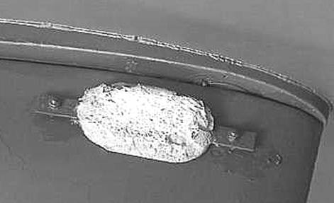
Used Sacrificial anode
For
optimum protection, firms who specialise in cathodic
protection can be brought in to measure the corrosion potential of the hull and
apply scientific principles to the size and placement of anodes.
Points
to note:
• Anodes should be in good electrical
contact with the hull.
• Anodes should not be painted.
• Anodes should lose weight between
dockings.
• If anodes are unchanged, have a white
chalky coating or are covered with weed or slime, they have reached the end of
their useful life.
• Anodes should be replaced regularly to
refresh the sacrificial material.
• Anodes will only ‘protect’ metal surfaces which are either
directly wired to the anode or are contained in the same electrolyte such as
sea water.
Accordingly,
machinery which is prone to corrosion such as the engine block, the heat
exchanger or bilge will need their own sacrificial anode.
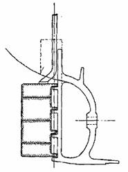
2.4 Measuring Sterntube
Bearing And Tail Shaft Wear

Propeller shaft, strut and propeller
The
sterntube is a steel tube which supports the
propeller shaft using bearings. The sterntube also
provides a seal preventing sea water from entering the vessel where the
propeller shaft passes through the hull.
In
the sterntube there are usually two bearings
supporting the propeller shaft (tailshaft):
• one is located
at the forward end, behind the gland where the shaft penetrates the aft engine
room bulkhead
• the other is at the after end of the
sterntube.
The
forward bearing is not accessible unless the tailshaft
is removed. As it only carries part of the weight of the shaft, wear is not
usually a concern. The aft bearing has to take part weight of the shaft and the
whole weight of the propeller and wear (if any) takes place in this bearing.
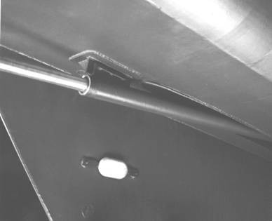
Propeller
Shaft Emerging from Stern Tube
• Tailshafts
(other names, screw or propeller shafts) are withdrawn for inspection of shaft
and bearings at 4 year intervals. If the vessel is docked or slipped within
that period it is standard practice to check the weardown
of the aft tailshaft bearing.
• The tailshaft
can move inside the bearing up to 6% of the diameter of the tailshaft.
For example, if a tailshaft is 50mm in diameter, the
permissible movement between the tailshaft and the
bearing is 3mm.
• If the movement exceeds 6%, then the
bearing needs to be replaced.
• Worn bearings may result in vibration in the propeller shaft.
The
reason for measuring wear down is that any sag of the shaft (due to the weight
of the propeller) increases the stress in the shaft. The wear down is a measure
of the sag (also called deflection).
The
shipbuilder provides a maximum deflection that must not be exceeded. If
exceeded the possible consequences are fracture of the shaft and loss of the
propeller.
A
common method of measuring the weardown is to clamp a
dial indicator gauge to the hull or sterntube so that
the pointer rests on the top of the shaft between the sterntube
and propeller. Note the reading on the dial, then jack up the propeller until
the resistance to jacking increases. Note the new reading. The difference is
the weardown.
Note
that the weardown as measured is the sum of the wear
in the bearing and any shaft wear.
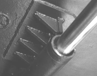
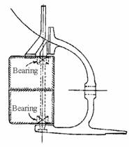
Propeller Shaft and Bearing in Stern Tube
Oil Lubricated Tailshafts
These
tailshafts have a mechanical seal at each end.
The
standard method of checking wear is by depth gauge.
A
collared plug in the gland housing or the stern tube just forward of the gland
is removed. The depth from the face of the plug boss to the top of the shaft is
measured.
This
should be compared to the original measurement when the shaft was installed.
The difference is the weardown.
Water Lubricated Tailshaft
The
aft bearing is usually accessible via the small gap between the aft end of the
stern tube and the front end of the propeller boss.
If
a rope guard is fitted over this gap, it must be removed.
The
tail shaft rests on the bottom half of the bearing. The gap between shaft and sterntube bush can be measured. This is done by using long
feeler gauges inserted at the top of the shaft.
Many
bearings have longitudinal grooves to allow water to circulate. Ensure the
measurement is taken at the bearing surface and not the groove.
If
the gap mentioned above is too small to allow access of the feeler gauges there
is another common method of measuring the weardown.
This method involves clamping a dial indicator gauge to the hull or sterntube.
The
pointer needs to rest on the top of the shaft between the sterntube
and propeller. Note the reading on the dial then jack up the propeller until
the resistance to jacking increases. Note the new reading. The difference is
the weardown.
Note: Weardown
as measured in all cases above is the sum of the wear in the bearing and any
shaft wear.
2.5 Opening Side Valves For Survey And
Maintenance
As
a general principle all the side valves on a vessel should be opened up and
overhauled at each drydocking. These valves are sea
inlet and overboard discharge valves for pumps such as:
• bilge
• general service
• fire
• ballast
• sea water cooling, etc.

Side valves
This
also includes all scupper pipes which have non-return valves fitted.
Be
aware that there are different types of valves used on vessels. You should
become familiar with the various types of valves used. In need, refer to your
facilitator for assistance.
These
steps should be followed during valve maintenance.
|
Step |
Action |
|
1 |
Open all valves by removing the
valve cover. |
|
2 |
Dismantle spindle. |
|
3 |
Dismantle bridge. |
|
4 |
Extract gland packing. |
Follow
these steps after inspection/survey has confirmed that the valves are in
satisfactory working condition or that repairs have been made as required.
|
Step |
Action |
|
1 |
The valve should be lapped to its
seat to ensure correct and accurate fit. |
|
2 |
Fit new gland packing as per
manufacturer’s instructions. |
|
3 |
The gland and all parts re-assembled
to the valve body. |
|
4 |
Close valve (if screw down type). |
It
is not necessary to remove the valve body from the piping if:
the body can
be visually inspected
the joint of valve to shell
plating is sound.
2.6 Checking Rudder Stock And Pintle Bearing Wear
The
rudder is used to guide the vessel’s direction. This is particularly important
if the vessel has only one engine and the balancing of power from a second
engine cannot be used to assist steering. It is important to include the rudder
system in routine maintenance to ensure it remains in satisfactory working
condition.
In
most cases, if a rudder fails it will occur under load and at a difficult time!
This may disable the vessel’s steering and result in a loss of control.
Rudders
generally fall into three categories:
|
Unbalanced
|
Semi-balanced
|
Balanced
|

If
the rudder has been poorly constructed or its condition allowed to deteriorate, the rudder stock could break loose within
the rudder itself. This will result in the rudder stock effectively rotating
inside the rudder while the rudder remains still. If there is any sign of
separate movement between the rudder stock and the rudder, the rudder should be
replaced.
The
wear of pintles or bearings can be checked by feeler
gauges. Clearance must be taken fore, aft, port and starboard as the pintles and stock are vertical and may not be lying central
in the bearings. Jacking the rudder hard one way (as for shafts) is an
alternative, but care must be taken to ensure that it is jacked squarely and
the rudder is not canted.
If
there is more than slight movement, the bearing should be replaced. If the
bearing fails the rudder will be free to move violently under force from water
action.
2.7 Attaching The Propeller To The Shaft
Unless
the vessel operates with jet propulsion, you need a propeller to convert the
engine power to move the vessel through the water.
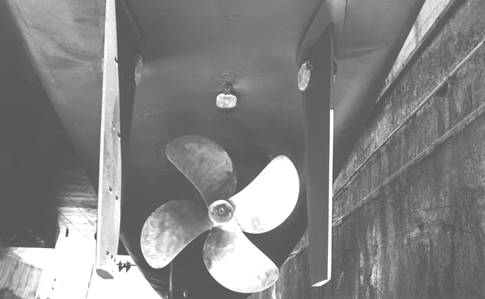
Propeller and rudder arrangement
The
most common method of attaching a propeller to the tailshaft
is by machining a taper on the propeller end of the shaft and a matching taper
in the bore of the propeller. The taper is usually 1 in 12.
A
keyway and key is provided in the shaft with a matching keyway in the
propeller. These act as a guide for close fit.
The small end of the shaft is extended and threaded to take a nut.
The
propeller is pushed hard up on the shaft taper by tightening the nut. A locking
device is fitted to prevent the nut from slackening. There are many methods of
locking the nut. Most involve a setscrew or Allen screw that penetrates both
the nut and the propeller boss.
Once
the nuts are locked into place, the propeller is securely fastened onto the tailshaft and ready for service.
Propeller Assembly

Deck Machinery
3.1 Operation Of An Anchor Windlass And Cargo Winch
Anchor
Windlass
The
USL Code requires an anchor windlass to be fitted where the weight of the
anchor is greater than 30kg and, where the anchor weighs more than 50kg the
windlass must be power operated. Two anchors are required except for very small
vessels.
An
anchor windlass is comprised of a frame that supports a mainshaft
in bearings. Mounted on the shaft are:
• a cable lifter
drum (often called a “gypsy”), grooved and slotted to fit the anchor cable
• a brake drum secured to or forming part
of the cable lifter, with brake band, housing and operating mechanism attached
to the windlass frame
• a clutch
usually a "dog" type clutch/s to release the cable lifter and allow
it to rotate freely on the shaft
• for manual operation, a crank handle at one
or both ends of the shaft
• for power operation,
a electric or hydraulic motor coupled to the shaft; where two anchors are
provided the usual arrangement is for the motor to be located between the
windlasses for each anchor or be located aft of the windlasses. In this latter
case the motor drives the main shaft through gearing.
On
vessels where mooring ropes/wires are too heavy to handle manually, the main
windlass shaft is often extended at each end to take warping drums for handling
the mooring wires/ropes on arrival/departure from port.
The
warping drums may be locked on the shaft or are de-clutchable.
The latter arrangement is the safest.
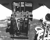
Typical anchor windlass
Safe
Operation
Anchor Operations
Before
starting the motor, check that the area around the windlass is clear of
ropes/wires and other gear, and that there are no ropes or wires on warping
drum/s.
In
some cases, it may be necessary to start the motor to take the load. Ensure all
clutches/brakes are in the appropriate positions and check that chain stoppers,
devils claws and/or lashings are removed and cable is clear.
Start the motor.
At
all times, stand aft of windlass and ensure you are not in line with the run of
the cable. The windlass operating position is suitable.
Keep
clear of warping drums if they are not de-clutchable.
When lowering cable, check that dog clutch is
clear of cable lifter and release brake sufficient to control the run out speed
of the cable. If lowered too quickly it may whip and jump on and off the cable
lifter.
When riding at anchor, fit the chain stopper or
devils claw and/or lashings to secure the cable. Allow some sag of the cable
between stopper or claw and the windlass so that the anchor and cable weight is
carried on the stopper or claw. This is so that the windlass is isolated from
load and shocks.
When hoisting cable, ensure the dog clutch is
engaged with cable lifter and brake is off. Release chain stopper or devils
claw and/or lashings. Start hoisting cable. If the anchor housing is not
visible from the windlass operating position, ensure that an assistant is
available to signal when the anchor appears and ensure the anchor is housed
securely.
Fit
chain stopper or devils claw and/or lashings to secure the anchor. Release
clutch so that anchor weight is carried on its stopper. The brake should be on
in case the stopper or lashings should accidentally slacken or come adrift.
General
Precautions
The
windlass is in an exposed position on the foredeck or forecastle. The deck area
is often wet and could be slippery. Wires, ropes, cable and fittings are hard
to handle. Therefore as a minimum non-slip footwear,
heavy duty gloves and clothing that is not to loose to get caught in the
rotating machinery should be worn.
Cargo
Winch
On
smaller vessels a cargo winch is normally used in conjunction with a swinging
derrick and like the windlass is comprised of a frame that supports a shaft in
bearings. Mounted on the shaft are:
• a
winding drum fixed to the shaft, usually between the two bearings. The drum
may be grooved to seat the wire rope better.
• a
brake drum secured to the winding drum, with brake band and housing
attached to the winch frame. The brake is usually foot operated.
• an electric or hydraulic
motor coupled to one end of the shaft.
The
electric motor and in many cases the hydraulic motor is fitted with a solenoid
operated magnetic brake that comes into operation whenever the motor controller
is brought to the stop position. This is to prevent slippage if the winch is
supporting a load. The foot brake can be used for fine control or in an
emergency.
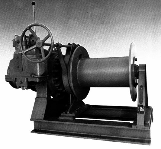
Typical Cargo Winch
Safe
Operation
Check
that the end of the wire (common name: runner) on the winding drum is securely
fastened to the drum. At least three turns should remain on the drum when the
runner is at the maximum operating length of the rig.
From
the operating position of the winch, take note of the run of the wire. This is
to ensure that should the wire run loose, you will not be in its path.
Clear
all loose wires and other equipment not necessary for the operation of the
winch from the working area around the winch.
The
general conditions as noted for the windlass apply to the operation of the
winch.
3.2 Dangers Of Incorrect Operation
Some
of the safety requirements and possible dangers arising from normal operation
of windlasses and winches have been discussed previously. The main danger is
damage to the equipment or personnel.
In
general, deck equipment is robust and will tolerate some rough handling but
care must still be taken.
Most
safety problems that arise are from incorrect operation, such as:
• Overloading the windlass when breaking
the anchor from the ground, or pulling the anchor hard home into its housing.
• Uncontrolled dropping of an anchor. The
cable may whip and snake, injuring personnel who may be standing close.
• Riding the brake when a winch is under
load. This could stall the motor at a critical moment in the operation.
• Overloading a winch such that the wire breaks. A wire
breaking under load will whirl wildly in all directions and could severely
injure personnel in its path.
Equipment
will serve you well if maintained, treated and operated with respect.
3.3 Routine Maintenance
Deck
machinery is fairly robust, but regular routine maintenance will serve you
better over time.
Windlasses and
winches
• Grease or oil the main bearings.
• Inject grease into all grease points.
• Oil all linkages that do not have grease
points. Use a penetrating oil if normal lubricating
oil is not effective.
• Oil or grease the threads on spindles of
brake operating gear.
• Check motors, both electric and
hydraulic in accordance with the manufacturers
instructions.
• Loose gear (such as shackles, blocks,
swivels, chains, and wires) should be examined regularly, stripped down,
inspected and oiled or greased in accordance with the periodic inspection
requirements.
• Test and inspect all running equipment under no load to
ensure it is operating freely.